I am healthcare professional, a general and orthopedic surgeon with over 24 years of active experience. We have been using an FDA approved software for complex surgical planning for the past 8 years.
However, due to its increasing cost per seat, we were looking for alternative and free solutions and came across 3D Slicer. I appreciate what Slicer’s existing features provide, and we started evaluating it just a couple of months ago. Besides the great functionalities, I have found subtle differences between these two.
In 3D Slicer, I applied threshold and island effect and exported the STL(s), then loaded it back into to the FDA approved software. In the FDA approved software, the same effects are applied, and we found a significant difference in contour of both the STL(s). Please find the comparison images below:
The yellow contour is from the FDA approved software STL, and the red contour is from 3D slicer STL
I am not a technical person but from the above image, we can see that there is an approximately 1-pixel difference between the two contours or we can say the contours are shifting from each other.
Here are the properties for the two different tested STL(s):
FDA approved software STL properties:
Slicer STL properties:
STL ‘Conversion setting’ of the FDA approved software:
Based on the above geometry images, the bounding box and volume geometry estimation appear to be approximately the same.
So how can we have the same STL output as the FDA approved software so that slicer can fit in our protocol.
I’ve used slicer version 5.4.0 and also verified in the 5.6.1 & 5.7.0 versions.
Dataset link: dataset.zip - Google Drive
margin tool from dynamic modeler module with a 3D model of the skull and a small positive value
using a very small up-scaling transform on the Transforms module
segment editor effect ‘margin’ inside segment editor module with your skull sementation and then cover to a model and check if you can get the overlay you want
Last option is less likely to be your solution because it will change triangle count from your original segmentation
Thanks for reporting - are you able to share the STL files from both systems too?
It’s possible that the two systems use different algorithms or different interpretations of the parameters and care must be taken to make sure they provide results that are consistent with your needs.
One suggestion would be to scan a phantom with known dimensions and confirm what the accuracy of any particular method will be. As @mau_igna_06 points out, there may be several ways of approximating the surface. It may also be important to consider the CT scan protocol and reconstruction options as they may influence the estimation of the surface.
Also, these CT pixels are about .5 mm so the differences appear in most cases to be about .1 or .2 mm or less. It would be interesting to hear your thoughts on the accuracy you need to achieve.
Also note the disclaimer that while the 3D Slicer community strives for accuracy, it is not an FDA approved application and you need to use consistent with the laws and any institutional policies that govern your work.
The red contour, from Slicer, looks more aggressively smoothed than the yellow contour, and that may be the main difference between them. You might explore reducing the smoothing that Slicer applies when converting from binary labelmap representation (the direct result of the threshold) to the closed surface representation (what is shown in the 3D view, and what is created as the exported surface model representation). You can change this smoothing factor by clicking on the dropdown on the “Show 3D” button in segment editor, and then changing the slider value between 0 and 1 (default is 0.5, and 0 means no smoothing). More conversion settings (such as a decimation factor) are accessible in the Segmentations module, if you click the “Update” button next to the “Closed Surface” line in the “Representations” section, and then click the ‘Binary labelmap → Closed surface’ path in the window that pops up.
If you can load your FDA STL into Slicer, you can see if you can get a better match by iteratively changing the Smoothing factor on the Slicer segmentation and directly comparing. To get some of the sharp features visible in the FDA STL, you may need to turn off smoothing entirely. I would also suggest considering what representation you feel is most faithful to the surgical reality. Does the skull have small sharp features more like the yellow line? I would also second @pieper 's suggestion to consider what level of accuracy you expect from an image with a voxel resolution of 0.5 mm.
Yes, the the segmentation results look about the same to me, with the difference being smaller than a single voxel.
See intensity profile along a line orthogonal to the bone surface. The width of the transition zone from soft tissue to bone is about 2mm. It would be hard to tell where is the exact boundary: at the peak intensity, where the peak starts, at half maximum, …? Each definition could be valid and the difference between them can be up to a millimeter.
@vikas26 I’ve analyzed your report very thoroughly and could reproduce a scaling inaccuracy of up to about 0.7% when not using “surface nets” smoothing (Conversion method: 0 or SurfaceNets smoothing: 0). This error typically means subpixel size, but we take any unnecessary processing inaccuracies very seriously and do everything to avoid them.
I’ve submitted a detailed report to VTK developers, who maintain the affected smoothing filter (vtkWindowedSincPolyDataFilter). Hopefully we’ll hear from them soon:
Until then, you can use Conversion method: 1 and SurfaceNets smoothing: 1 to avoid this processing inaccuracy.
We have found that by using a different window function in the low-pass filter in vtkWindowedSincPolyDataFilter in VTK, we can avoid this slight change in the smoothed surface. The change has been integrated into VTK library and Slicer will be updated within a few days to use this improved filtering.
Thank you mau_igna_06, pieper, mikebind, lassoan for the invaluable solution provided.
We aim for a stringent standard, adhering closely to FDA-approved software guidelines, with an error rate maintained below 0.01%.
We extend our heartfelt appreciation to @lassoan for the diligent integration of improvements into the VTK library. Following our thorough testing, we are pleased to report that the previously noted contour shift appears to be resolved satisfactorily.
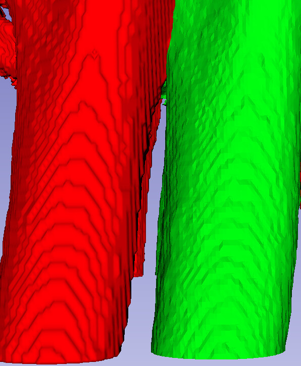
However, we wish to address another concern regarding the presence of step-like structures on the object’s surface.
Red represents the slicer with Zero smoothing.
Green represents the FDA approved software without any smoothing.
Upon activating the wireframe representation, it becomes apparent that the FDA-approved STL selectively stitches only the sharp edges, thereby mitigating the step-like structures, as illustrated in the accompanying image.
0.01% error is not even remotely feasible in anything related to clinical 3D medical imaging.
For example, if you work with images of 0.5mm voxel size then you could not possibly reach less than 1% error on a 50mm distance measurement.
If you work with any automated clinical image processing algorithm then the success rate is acceptable if it is about 1-5% (of course you need to make sure that you can detect error and make corrections, so this error will not be the final success rate of the procedure).
If you 3D print a part then you would have trouble going below 0.1mm error, which means 0.2% error for a 50mm part size.
We could say that a single basic software processing step (e.g., store a mesh in file and read it back) should work with less than 0.01% error, which should be very easy to satisfy as floating-point computations can be performed with magnitudes less error.
In Slicer, disabling smoothing means that the original continuous signal is not reconstructed at all, you just display the discrete sampling points. You must enable smoothing to get the correct surface. It is not some user preference that some people like it smoothed others prefer without smoothing, but if you don’t smooth then you get incorrect results.
Probably the other software just does not let you disable smoothing (lowest smoothing setting still applies some smoothing). It is hard to even tell which software works better, maybe inspecting zoomed-in cross-sectional views could help. However, validation should be always done with a reasonable tolerance for clinical use (not 0.01% but more like 1%) and with that the two software should produce equivalent results.
I was looking into this question and decided to give it a shot.
From what I’ve seen, it seems like 3D Slicer uses a method based on right angle triangles to create meshes, while the FDA software mentioned earlier might use a different method called tetrahedral meshing.
Do you think these different ways of calculating meshes could affect how smooth and accurate the final results are?
I think, since these software use different algorithms for meshing, it’s important to understand how this might affect the quality and accuracy of the meshes they produce.
I’m particularly interested in how the choice of meshing method might affect things like how smooth the surfaces are, how accurate the shapes are, and how fast the software can do its calculations.
If you have any insights or corrections on any of this, I’d really appreciate it. What is your opinion on this @lassoan?