Hi,
I have been working with Autoscoper for my PhD project, tracking foot and ankle bones using Biplane Fluoroscopy.
I have been going through the process of tracking with Autoscoper, and am having trouble with the Pre Processing.
The volumes are generated properly, and the tracking went well. My issue is with the cropping done to the volumes. The transform to get the tracked data in Autoscoper back into CT space requires a transform to account for the cropping. Visually this looks like a simple translation, and can be done using the new cropped volume origin. This I what I thought was being output into the transforms folder alongside the cropped volumes. The transforms being output do not match the origin and volume information if I look it up in Slicer. The outputted transform shows a stretch value in the z direction, which is a strange thing to have in a purely cropping step.

Is there a reason for this discrepancy between the transforms and volume information?
If the ones that the pre processing module outputs are correct, what it the way to apply this to get the tracking data back into CT space (the link between Slicer and Autoscoper Space) ?
Hi Robert,
We are in the processes of implementing a regression in the code introduced a few months back - we apologize for the inconvenience!
That said, you are correct
the.tfm written to the Transforms directory when processing your segmentation node into partial volumes contain the transform from your selected volume’s dicom origin to the corner of your tiff stack
Autoscoper parses the tiff stacks in a flipped manner and this is captured in the tra output. One method for managing this flip is to create a flipped proxy surface file (stl, wrl etc)
for bn =1:length(bones)
y_sz = size(bs.(bones{bn}).tif,1) * bs.(bones{bn}).tfmInv(1,1) ;
% z_sz = size(bs.(bones{bn}).tif,3) * bs.(bones{bn}).tfmInv(3,3) ;
CT_to_AUT_4x4 = RT_to_fX4(eul2rotm([0,0,pi]),[0 y_sz 0]);
bs.(bones{bn}).AUT2ACS =    CT_to_AUT_4x4* bs.(bones{bn}).pvolCS ;
bs.(bones{bn}).ptsinPvolvf = RT_transform(bs.(bones{bn}).ptsinPvol, CT_to_AUT_4x4(1:3,1:3), CT_to_AUT_4x4(1:3,4),1);
end
Applying the output tra to each respective “autoscoper space” stl will give appropriate bone model placement in dicom space
Once the regression correction is commit to the main branch we will also have a more thorough readthedocs entry to aid in this post processing.
Thank you for the quick reply!
I have a couple of follow up clarifications on this.
- Since the Autoscoper space parses the images flipped, can the flip x/y/z function on the Autoscoper new trial window (or in the CFG file) be used? Would this flip the coordinates back into the proper DICOM space and undo the need for another transform?
- Is the fix in the transform from the preprocessing to apply the origin as the z translation, and apply that to the flipped proxy surface (STL file) before applying the tracking?
Hey Robert,
I’ve not tried to use the flip booleans to ease post-processing- I can attempt and get back to you on that.
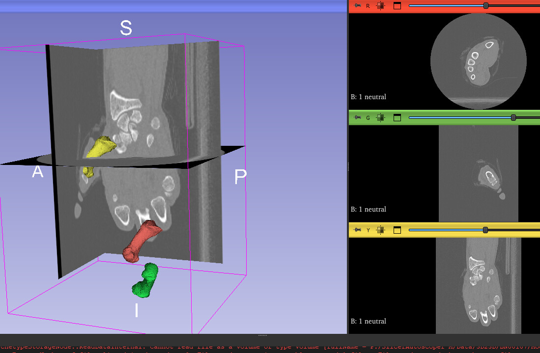
When you segment the CT, the model is in DICOM space ( mc1 model/seg shown in yellow)
The partial volumes tiff stacks are inherently without spatial resolution- the automatic tfm gives scale and translation info from image space to spatial coords (i.e. mm)
Without the tfm applied- the partial volume (shown in grayscale slices) is stretched inappropriately and index corner (0th row 0th colum and 0slice) is located at the origin.
WHen the tfm is applied (mc1_2) you’ll notice that the scale of the partial volume and it’s spatial resolution is identical to the segmented (yellow) mc1
The tricky bit concerns the red and green mc1. You’ll notice in the data node heirarchy, I’ve labeld the red mc1 with a Pvol prefix and the green with AUT
The red mc1 is the model you would get from the partial volume with properly scaled voxel information (0.39 0.39 0.625… ‘scale’ transfrom) , but corner indices still at 0,0,0.
The green is what AUT internally acts on (how it loads and stores the tiff - and what the tra operates on to
@jcfr
Thank you, the stretch factor now makes sense.
I have tried to replicate the yellow green and red models as in your photos. I have figured out the transform from the yellow to red. This is just the inverse of the transform automatically generated without the scaling factor.
The issue seems to be the transform between the red and green models. I applied an x and z flip to the model : [-1,0,0;0,1,0;0,0,-1]. As this seems to match your images.
When I multiply the tra tracking data to these transformed green models (which should now match the autoscoper space), they do not seem to be matching up with the tracking I see in Autoscoper world view. (I am doing TRA*GreenBoneModels).
Can you see anything wrong with this approach?
Hey Robert, we’re still working through some fixes.
Can you try updating the extension from the index and try again?
Hi Robert.
Assuming your volume has its origin at (0,0,0) and the proper scaling has already been applied, you should be able to follow the following steps in order to move it into the optimized position from Autoscoper.
You will need to put together an Autoscoper2Slicer transform. This consists of two operations:
- A 180 degree rotation about the X-axis (L-R axis).
- An Offset in the +X (R) direction computed by volDim * volSpacing for the x dimension.
Once you have this you should be able to apply it to your volume then apply the tra file and your volume should be in the correct place. Please checkout this comment on Github for a visual example.
Your transform hierarchy should look something like this once you are done (NOTE: I am using the inverse of a Slicer2Autoscoper transform for my Autoscoper2Slicer transform):
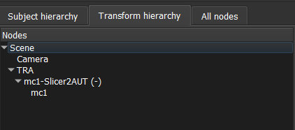
We are working on adding a feature to automatically export this transform to the Transforms directory. For the latest progress on integration, please checkout PR #109 on Github.
Definitely let me know how this works for you!
-Anthony
Hi,
I have been playing around with the transforms you mentioned and it is still not quite working.
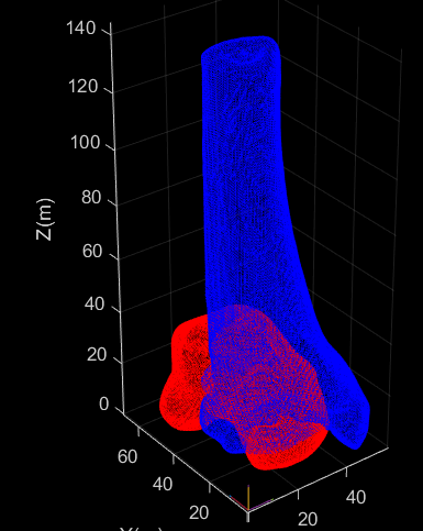
The first image here shows the original CT segmented volume (yellow), the automatically generated volumes from the pre processing (stretched, but centered at the origin), and the centered bone models (Red).
The next step would be to apply the Autoscoper to Slicer transform.
This was an x rotation, and a x translation (from the CT volume information - dimension*spacing)


This resulted in the bones being moved as expected, as shown in the green bones.
Then the TRA file for each bone is applied to each bone. (Blue) This results in them being transformed, but not to the expected neutral position.
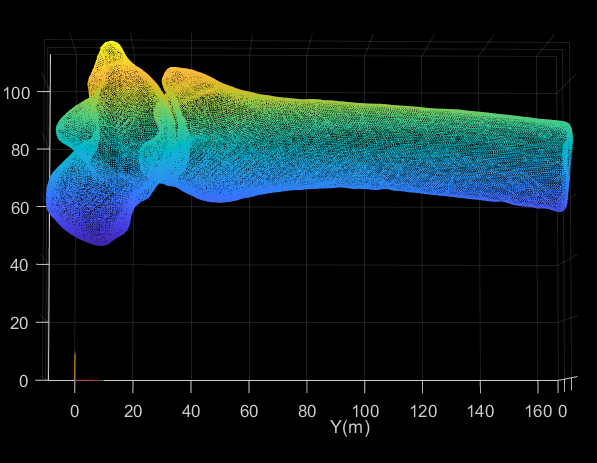
For reference, this is how the bones look in Autoscoper World View.
I am not sure now which step is being applied wrong, but any advice would be helpful on how to make these transforms work.
Thanks,
Robert
Robert, Would you be available to work one-on-one over zoom next week?
1 Like
Yes - Absolutely.
My email is robert.chauvet@ucalgary.ca if you want to schedule a meeting.
Robert
1 Like
Thanks Amy,
I have gotten the Transforms to work in MATLAB properly.
This involved importing the centered STL Files from SLICER (or the raw DICOM Positioned STL and translating it to the Origin in MATLAB)
Applying a transformation matrix of the following:
Rot_Tibia=eul2rotm([0,0,pi]);
Translation_Tibia=[0;46.898;0];
TRANSFORM_Tibia=[Rot_Tibia,Translation_Tibia;0,0,0,1];
The 46.898 comes from the y volume spacing multiplied by the y volume dimension. This is a different value for each bone.
This information can be found in the AUTOSCOPER pre processing module, in the Slicer2AUT transform.
The rotation is not the same as the Slicer2AUT transform output, as the transform gives you a [-1,0,0;0,1,0;0,0,-1] rotation, where the rotation needed is a [1,0,0;0,-1,0;0,0,-1].

Applying the TRA matrix to the bones, then positions the bones correctly as in the AUTOSCOPER space.
Bone_model_Tracked.Tibia.vertices= (Tracking_matx.Tibia*Bone_model_Transformed.Tibia.vertices’)';
Bone_model_Tracked.Talus.vertices= (Tracking_matx.Talus*Bone_model_Transformed.Talus.vertices’)';