I would like to know the rotation and translation of two segmented models, in numerical values. Could you please suggest the best way to do that.
Thanks
I would like to know the rotation and translation of two segmented models, in numerical values. Could you please suggest the best way to do that.
Thanks
You can align segments using Segment Registration extension then see the transformation matrix values in Transforms module.
Thank you Professor @lassoan.
It only gives translation along the xyz axes. Is it because the displacement here is based on the centre of mass/ centroid? If I want the rotation of a the rigid body/ bone- what should I do. In the transforms matrix rotation is indicated as 0 in all 3 axes. Do i have to define an axis of rotation please? Thanks
Tom
The sliders are only for changing the transforms, they don’t necessarily represent the current state.
The transformation is specified by a 4x4 homogeneous transformation matrix (top-left 3x3 matrix defines orientation and scaling, top-right 3x1 vector defines translation).
Apologies Prof Lasso @lassoan.
I did not understand I am afraid- I am trying to see the change of position in terms of translation and rotation of two segments. Could you please let me know the numerical values given in the transform correspond to the translation of segment 2, compared to segment 1. If not, what should I do to calculate that, please? Also, how can I calculate rotation, please? Apologies for taking your time- I am a medical person with no software background. Thanks a lot.
Hi All
Sorry about all this amateur questions and new post. But could someone explain me how to get the displacement of one segment to another in terms of rotations please. I did segment registration and got a the linear transform, but I don’t know how to calculate Euler s angles of rotation of my segment out of this numbers. Thanks a lot
You can get Euler angles orientation matrix using this code snippet:
transformNode = getNode('LinearTransform_3')
transformMatrix = vtk.vtkMatrix4x4()
transformNode.GetMatrixTransformToParent(transformMatrix)
transform = vtk.vtkTransform()
transform.SetMatrix(transformMatrix)
orientation = transform.GetOrientation()
print(orientation)
Note that the same orientation can be encoded using many different combinations of rotations, even Euler angles have many variants.
If you need to use a particular convention then you can implement the angle computations from the corresponding mathematical formulae directly you can access orientation matrix element in the transformMatrix object in the example above.
I can’t thank you enough Professor @lassoan
I will try this- I don’t get all the mathematical side of it, but my project is to segment bones and calculate the translation and rotation with time points. so I m planning to take the translation values , off the transform module top right and rotation in Euler angles with this. hope my steps are correct. Thanks again.
Hi Prof @lassoan
I have tried to use this code for my calculations of Euler angles.
When I apply to my linear transformation of known roll yaw and pitch, the values I get is only 2 values correct. What could be the possible.
Thanks
The same orientation can be encoded using many different combinations of rotations, even Euler angles have many variants. The code snippet above uses ZXY rotation order - see complete conversion between matrix and Euler angles representation in this post:
Thank you Professor @lassoan
Hello Andras,
I’m wondering what the Z, X, and Y axes are in terms of LR, PA, and IS axes?
Thank you,
Michele
Slicer’s coordinate system axis directions are right, anterior, superior.
Yes, but you mentioned in your earlier post that the code snippet is uses the ZXY rotation order, and I was wondering which axes these correspond to, in the slicer axes?
Thank you,
Michele
I meant first, second, third coordinate system axis by X, Y, Z . Therefore, X=R, Y=A, Z=S.
Oh my apologies. Thank you very much!!
Michele
Sorry to revive this, but how would you put this into the XYZ order
Could you describe a bit more detail ecset you want to achieve?
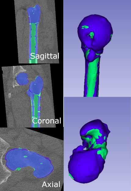
So currently i have 3 models of a femur. A preoperative, postoperative and planning. I made a coordinate system that i made from three points of this femur. I allign the coordinate system with the World coordinate system and allign all my femoral shafts as shown here:
All transformations have been hardened and i measure from the point ive set. Through alpaca i allign the proximal parts to see how they’ve moved.
I return the euler angles from the matrices with the script as described above. This gives the euler angles in a ZXY order, i would like it to be in a XYZ order if possible.
Thank you so much for your help.
Each column of the transformation matrix contain direction of one coordinate system axis. Therefore, you can use the same vtkTransform.GetOrientation() method and just reorder the columns of the input transformation matrix. It is probably a good idea to keep the transformation matrix right-handed by swapping columns even numner of times; or swapping columns odd number of times and inverting the direction of one axis.
Note that Euler angles is generally considered to be a poor representation of orientation. Problems include gimbal lock and that the angles don’t have an intuitive meaning when more than one angle is significantly different than 0 (because the second and third rotations are performed around already rotated axes). If you want to characterize misalignment, I would recommend measuring angle between axes in anterior-posterior and lateral projections - similarly how you would measure angles in two planar X-ray projection images. To compute these angles you would not need to arbitrarily choose an ordering of rotation axes.