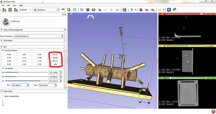
Rotation matrix from the Transform Module

Operating system: windows 7
Slicer version: 4.8.1
Expected behavior:
Actual behavior:
Hello,
I create a needle model to insert it to a specific region in my 3D model in slicer. This way, the position of the needle tip and the orientation of the needle is important. The desired pose of the needle is obtained by the translation and rotation part of the transform module (the needle model is defined as the transformed i.e the active transform is applied to it.)
The problem is that:
First: if i save the txt.file of the linear transform and load it in matlab, it can be undestood that the rotation part is not really the rotation matrix i.e the inverse and the traspose are not equal.
(I convert the matrix from the LPS to RAS and the one that i load in matlab is exactly the same as seen in slicer)
Second: The result is not the same as i use the invert in slicer in comparison to the inverse of the matrix from matlab.

I would be appreciated if anyone could help me…

See this topic for explanation and solution: Saving Linear Transformation Matrix

Thanks Mr. Lasso.
Actually i saw the topic and i use it for the conversion to have the same rotation matrix in matlab. But i don’t want to use the Matlab bridge extension. I need to know which euler-angles the Slicer rotation matrix is based on?

You don’t need to use the entire extension but just use the few lines of code that inverts axes and the matrix.

Euler angles are not well suited for representing arbitrary orientations (suffers from gimbal lock and there are multiple parametrizations for the same orientation). I would recommend using orientation matrix or quaternion representation.

Thanks,
Actually, i’m working on a robotic project and i should define the orientation of my tool.
this way i want to know how the transformation module creates the rotation part based on the degrees which can be defined by the users?

Slicer stores transformation as a 4x4 homogeneous transformation matrix, you can use this to compute robot joint coordinates from this matrix (inverse kinematics).

Thanks,
I think that i misunderstood your previous request.
i found that the slicer works on Quaternions based on the Euler angles defined by users.

In Matlab, This could be obtained by converting the transformation matrix of slicer to the Quaternion definition and then find the Euler angles of the related Quaternion.
Thanks a lot from your guidance…

Hello again,

I came to the problem again when using the transform module.
when i save the transformation matrix even the translation part is changed. why is this happen? is there any way to obtain the same translation part (position) which can be seen in slicer software?
Actually i need the position of the needle tip in RAS coordinate system.

here is the position (red square box) which i can be seen in slicer:

and here is the piece of matlab code to convert LPS to RAS for the data which have been saved as linear transform_3. it can be obviously seen that the position is totally changed while the other arrays in rows are the columns of the transform module in slicer.
slicer%20pose%20matlab

I know that i ask a lot but i need to use this module correctly. and i am so grateful from your guidance, Mr. Lasso. @lassoan

It seems that you don’t put the matrix elements into their correct location because the orientation part is transposed. If the orientation part is incorrect then the translation is computed incorrectly, too. Probably you need to swap the row and column indices.

Is the needle model origin at (0,0,0)? You can verify this by creating a “Coordinate system” model using “Create models” module in SlicerIGT and apply the same transform to it. Axes of the coordinate system model should intersect at the needle tip.

The transposed Matrix was from the inverse in Matlab code. So the arrays are now at the correct locations.
M2
I add a coordinate system to the of the needle by applying the same transform to both of the needle and coordinate system model.
S2
But the problem is still exist…Is there any translational offset between the RAS and LPS coordinate systems? I mean that multiplying the matrix from the saved file to the diagonal matrix is just because of the rotational difference between the RAS and LPS and it doesn’t have any effect on the translation values…
Another surprising is that the position is changed as changing the rotation part. I mean that if i changed the orientation of the needle and entering the same position in the Matrix, the position data will be different in saved file from the previous file, even they are entered the same in slicer but with different rotation part…

As I wrote above, there is a mistake in how the B (fromParent_LPS) matrix is constructed in your example above. The correct fromParent_LPS matrix looks something like this:

[[  -0.65   -0.44    0.62 -107.59]
 [   0.62    0.15    0.76 -227.31]
 [  -0.43    0.89    0.18  -88.75]
 [   0.      0.      0.      1.  ]]

The inverse operator is responsible for computing the “to parent” transform (displayed in Slicer) from the “from parent” transform (stored in the ITK transform). Do not remove it. The first formula that you used above was correct:

toParent_RAS =
= LPS_to_RAS * toParent_LPS * RAS_to_LPS
= LPS_to_RAS * inv(fromParent_LPS) * RAS_to_LPS
= diag(-1,-1,1,1) * inv(fromParent_LPS) * diag(-1,-1,1,1)

toParent_RAS => shown in Slicer
fromParent_LPS => saved in ITK transform

1 Like

Thanks a lot Mr. Lasso.
By following your suggestion, now it is work…

1 Like

Hi Mr Lassoan,
Refering to Unity Code (OpenIGTLinkConnect.cs) taken from this Github (OpenIGTLink-Unity/OpenIGTLink-Unity/Assets/Scripts at master · franklinwk/OpenIGTLink-Unity · GitHub)

This is the Unity .cs code

// ##### #################################################
Matrix4x4 matrix = new Matrix4x4();
matrix.SetRow(0, new Vector4(m[0], m[3], m[6], m[9] / scaleMultiplier));
matrix.SetRow(1, new Vector4(m[1], m[4], m[7], m[10] / scaleMultiplier));
matrix.SetRow(2, new Vector4(m[2], m[5], m[8], m[11] / scaleMultiplier));
matrix.SetRow(3, new Vector4(0.0f, 0.0f, 0.0f, 1.0f));

Matrix4x4 IJKToRAS = new Matrix4x4();
IJKToRAS.SetRow(0, new Vector4(-1.0f, 0, 0, 0));
IJKToRAS.SetRow(1, new Vector4(0, -1.0f, 0, 2));
IJKToRAS.SetRow(2, new Vector4(0, 0, 1.0f, 0));
IJKToRAS.SetRow(3, new Vector4(0.0f, 0.0f, 0.0f, 1.0f));

Matrix4x4 matrixRAS = matrix * IJKToRAS;

// ##### #################################################

comparing to the steps that you described above
toParent_RAS =
= LPS_to_RAS * toParent_LPS * RAS_to_LPS
= LPS_to_RAS * inv(fromParent_LPS ) * RAS_to_LPS
= diag(-1,-1,1,1) * inv(fromParent_LPS) * diag(-1,-1,1,1)

It looks like the steps for conversion is not complete there.
I am getting different values in Unity, compare to the value from NDI Track App.

And, the value I am getting from NDI Track App is the same for Slicer and Unity.
Does it mean that I need to set the Needle origin in Slicer or can I set this in PLUS server setting? so that I get same values for Needle coordinates in NDI Track, Slicer and Unity?

FYI - The reference coordinate is correct and similar for all three - NDI Track, Slicer and Unity (if I am using the matrix and not the IJKToRAS)
if I am multiplying them with IJKToRAS - none of the values are the same in all 3 Apps.

Thanks

1 Like

image

After StylusTip calibration in Slicer following this tutorials (Slicer Tutorial #5: Receiving the Connection and Calibrating the Stylus — Andy's Brain Book 1.0 documentation & https://onedrive.live.com/view.aspx?resid=7230D4DEC6058018!3128&ithint=file%2Cpptx&authkey=!AMy-wgNHStEKsPU ) - I got this scene.mrml file that contains the matric for the StylusTip, and I need to apply them as a CoordinateDefinitions in PLUS Server.

What does the StylusTip matric value means and which represent the x,y,z, offset that I need to use in PLUS server?

Thanks.

I cannot comment or investigate why the conversion was done like that in OpenIGTLinkConnect.cs. If you don’t think it is correct then feel free to modify it as you see fit and then you may consider submitting a pull request to that repository, but I’m not sure if that project is still active.

You cannot “set the Needle origin”. You specify coordinate systems (see coordinate systems specifications that we use in all Plus and SlicerIGT projects), such as Needle and NeedleTip and then compute transform between them using various calibration tools. You can accept and use these conventions, but you are free to establish different conventions - they will work, too, as long as you are using them consistently.

IJKToRAS is for converting voxel (IJK) coordinates to anatomical (RAS) coordinates of an image volume. We don’t talk about images here at all. We do not have coordinates in IJK coordinate system here, so you cannot use the IJKToRAS matrix for anything that is discussed in this topic.

If you store a NeedleTip to Needle transform in the Plus configuration file (e.g., by performing pivot calibration in fCal; or performing pivot calibration in Slicer and then sending or copying the transform to Plus) then you can send the NeedleTipToReference transform to Slicer.

If you just store NeedleTip to Needle transform in the Slicer scene then you can use it by assembling a correct transform hierarchy.

Hi Mr Lassoan,

Thanks for the reply.
It is a great help in getting us a useful result. Thank you.

Previously -
a) Only Reference value for NDI, Slicer and Unity is the same
b) All other sensors for both Slicer and Unity which share the same value contradicts with NDI.

The reason behind this is due to - PLUS setting that does not use Reference.
So, with this new PLUS setting, all sensors refer back to Reference, and got all its value corrected to match the NDI.

<PlusConfiguration version="2.1">

  <DataCollection StartupDelaySec="1.0">
    <DeviceSet 
      Name="NDI_to_Unity_PLUS"
      Description=""
    />
    <Device
      Id="TrackerDevice" 
      Type="AuroraTracker"
      SerialPort="6"
      ToolReferenceFrame="Tracker" >
     <DataSources>
        <DataSource Type="Tool" Id="Probe" PortName="0" />
        <DataSource Type="Tool" Id="Reference" PortName="1" />
        <DataSource Type="Tool" Id="StylusSensor" PortName="2" />
       
      </DataSources>
      <OutputChannels>
        <OutputChannel Id="TrackerStream">
          <DataSource Id="Probe" />
          <DataSource Id="Reference" />
          <DataSource Id="StylusSensor" />
        </OutputChannel>
      </OutputChannels>
    </Device>
	    
		<Device
      Id="CaptureDevice"
      Type="VirtualCapture"
      BaseFilename="RecordingTest.igs.mha"
      EnableCapturingOnStart="FALSE" >
      <InputChannels>
        <InputChannel Id="TrackerStream" />
      </InputChannels>
    </Device>
	
  </DataCollection>

   <PlusOpenIGTLinkServer 
    MaxNumberOfIgtlMessagesToSend="1" 
    MaxTimeSpentWithProcessingMs="50" 
    ListeningPort="18944" 
    SendValidTransformsOnly="true" 
    OutputChannelId="TrackerStream" > 
    <DefaultClientInfo> 
      <MessageTypes> 
        <Message Type="TRANSFORM" />
      </MessageTypes>
      <TransformNames> 
	  <Transform Name="StylusToReference" />
        <Transform Name="ProbeToReference" />
        <Transform Name="ProbeToTrackerTransform" />
        <Transform Name="ReferenceToTrackerTransform" />
        <Transform Name="StylusToTrackerTransform" />
        </TransformNames>
    </DefaultClientInfo>
  </PlusOpenIGTLinkServer>
  
 <CoordinateDefinitions>
    <Transform From="Stylus" To="StylusSensor"
      Matrix="
        1 0 0 0
        0 1  0  0
        0 0 1 0
        0 0 0 1"
       Error="0.554951" Date="012617_105449" />
  </CoordinateDefinitions>
	
</PlusConfiguration>
<CoordinateDefinitions>
    <Transform From="Stylus" To="StylusSensor"
      Matrix="
        1 0 0 0
        0 1  0  0
        0 0 1 0
        0 0 0 1"
       Error="0.554951" Date="012617_105449" />
  </CoordinateDefinitions>

This coordinate setting does nothing becauase after trying a few values - it does not offset the needle, so we leave it at Vector.Identity (no change)

However, the Needle tip does not require any offset in Unity. although we first thought that this could be around 8.8cm back from the tip.