Hi,
I am trying to convert some tractography data from .tck to .vtk format. But I can’t get the correct results that match the image loaded in slicer. I’m not very familiar to vtk files and
slicer so I’m seeking for help. Here’s the efforts I’ve tried:
tckconvert -scanner2image
 Mrtrix provides a command to realize it. TCK files are in world coordinates and
 2imagemeans changing it to image coordinates(in mm). Then load vtk asmodelswith explicitly setcoordinate systemas RAS. But the problems are:
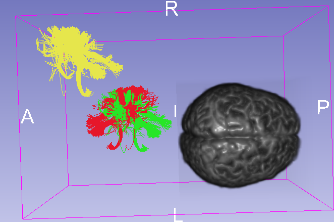
- Anterior and Posterior of the image volume seems wrong as you can see in Fig.1.
- Tracts(yellow) are above the back right of the image volume.


tckconvert -scanner2voxel, where2voxelmeans changing it to voxel coordinates. Also load vtk asmodelswith explicitly setcoordinate systemas RAS. Now :
- Tracts(blue) are smaller than it should be.
- different location from tracts(yellow).


- python vtk package:
reference here In reference, a TRK file was loaded and converted,here I replaced with a TCK file.
Now:

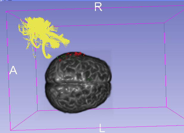
- Tracts(green) is in the back of the volume


- python vtk package:I tried to move original coordination in voxel coordinates randomly ( maybe change RAS to LAS, and move tracts backward a little?
10is a number I test to match, really painful…) As the same, load it as RAS system.
Now:
-
Tracts(red) seems flipped over in A-P direction
-
If I set image as centered when loading image volume, suddenly the tracts(red) can match the volume. However, I still don’t understand the rationale.


It took me a long time try to figure it out, but I failed… My goal is to convert my tractography to vtk format, then I can use WhiteMatterAnalysis for parcellation. And I want to know:
- Which coordinate system 3D slicer uses to load and display a nifiti image?
- Which coordinate system VTK file could receive ?
- Which coordinate system should I choose when sending a VTK file as a
model? And what about asFiberbundles?
Anyone’ help will be very much appreciated!
Operating system: Ubuntu
Slicer version: 5.0.3