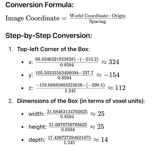
In data probe. we can see the image coordination, do you know or having script to know how it convert the real world coordination to image coordination?
My task is to get the boundingbox in 2D slicer from 3D segmentation. so e.g I get a segmentation bounding box coordination like: “box”: [
[
68.03462219238281,
105.50535583496094,
-159.68885803222656,
21.68463134765625,
21.6978759765625,
17.426727294921875
], but I don’t know how to map them back to the image coordination.
I find a guild in 3D visulization: tutorials/detection/luna16_visualization at main · Project-MONAI/tutorials · GitHub so then I convert a .obj file like: for one boundingbox, the 8 corner coordination(cube) like :v 78.87693786621094 116.35429382324219 -168.4022216796875
v 78.87693786621094 94.65641784667969 -168.4022216796875
v 57.19230651855469 94.65641784667969 -168.4022216796875
v 57.19230651855469 116.35429382324219 -168.4022216796875
v 78.87693786621094 116.35429382324219 -150.97549438476562
v 78.87693786621094 94.65641784667969 -150.97549438476562
v 57.19230651855469 94.65641784667969 -150.97549438476562
v 57.19230651855469 116.35429382324219 -150.97549438476562 and the nii.gz original file attrubute like this:
However, I use
I calculated , in Z -ray. it works, the bounding box contain 14 slicer which same to :
but, X,Y are wrong. however I find that in monai 3D slicer data probe. the conversion is correct. so I wnat to know how it convert?


