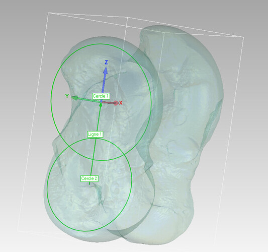
Model alignment to world coordinate system

Hello,

I’m a paleontologist working with surface model bones, and I need all my models to follow a certain alignment for analysis purposes.

I’m wondering if it’s possible to align a certain markup line to the world axis or to align certain points to the origin of the world?

Thank you so much in advance for your answer!

Julian KC

This is doable in many ways, couple easy options are:

  1. Create a transform from set of points on a reference and target (ie., fiducial registration).

  2. You can do it manually by using the interaction widget of the Transforms module.

Do you want to do this interactively (using GUI) or from a python script? For GUI you can use the manual options I described above… Programmatically there might be some examples in Python script repository.

If you can give some examples (screenshots of what you are trying to do), it would be easier to give more concrete answers.

Thank you very much for your prompt response.

  1. I apologize for not being clear earlier. I cannot manually align my models as it isn’t accurate enough for my needs.

  2. I don’t mind whether it’s done with or without a GUI. I’m currently learning Python, so it would be great to use it for this task and enhance my skills.

You can see exactly what I want to achieve in the first image:

  1. First, set the red point as the origin of the world coordinates (0,0,0).
  2. Then, set the green line as the Z-axis of the world coordinates.

The second image shows exactly what I want, but it’s done using another software (Geomagic Wrap). I would prefer to use only open-source software for my study, but it should give you an idea.

You can see two circles; I want to achieve that in Slicer too. I think I can manage that on my own, but if I can’t, I’ll discuss it in another post… haha.

I hope I was clear enough. Thanks a lot in advance for your help!

this post and specific answer seems relevant to your inquiry:

Thanks for your answer,

I already saw that but I didn’t understood how to use it and apply it to my models,
Sorry to ask that but can you be a little bit more specific ?

I tried this code :

import slicer
import numpy as np

Fonction to Create a translate transform

def create_translation_transform(x, y, z):
transform = slicer.mrmlScene.AddNewNodeByClass(“vtkMRMLTransformNode”)
matrix = vtk.vtkMatrix4x4()
matrix.SetElement(0, 3, -x)
matrix.SetElement(1, 3, -y)
matrix.SetElement(2, 3, -z)
transform.SetMatrixTransformToParent(matrix)
return transform

Fonction to Align with Z axis

def create_rotation_transform(angle, axis):
transform = slicer.mrmlScene.AddNewNodeByClass(“vtkMRMLTransformNode”)
matrix = vtk.vtkMatrix4x4()
axis = np.array(axis) / np.linalg.norm(axis)
c, s = np.cos(angle), np.sin(angle)
C = 1 - c
x, y, z = axis
matrix.SetElement(0, 0, xxC + c)
matrix.SetElement(0, 1, xyC - zs)
matrix.SetElement(0, 2, x
zC + ys)
matrix.SetElement(1, 0, yxC + zs)
matrix.SetElement(1, 1, y
yC + c)
matrix.SetElement(1, 2, y
zC - xs)
matrix.SetElement(2, 0, zxC - ys)
matrix.SetElement(2, 1, z
yC + xs)
matrix.SetElement(2, 2, zzC + c)
transform.SetMatrixTransformToParent(matrix)
return transform

Define point to align with origin (0.0.0)

point_origin = [13.311, -14.499, -1.052] # Remplacer par les coordonnées réelles du point

Define point of the line to align with z axis

point1 = [16.183, 0.719, 11.181] # Remplacer par les coordonnées réelles du point 1
point2 = [13.277, -14.627, -1.061] # Remplacer par les coordonnées réelles du point 2

Compute line direction

line_direction = np.array(point2) - np.array(point1)
line_direction = line_direction / np.linalg.norm(line_direction)

Compute the angle of the line

axis_z = np.array([0, 0, 1])
angle = np.arccos(np.dot(line_direction, axis_z))

Create and apply the fonction of translate transforme

translation_transform = create_translation_transform(*point_origin)
slicer.util.getNode(‘YourNodeName’).SetAndObserveTransformNodeID(translation_transform.GetID())

Create and apply rotate transform

rotation_transform = create_rotation_transform(angle, np.cross(line_direction, axis_z))
slicer.util.getNode(‘YourNodeName’).SetAndObserveTransformNodeID(rotation_transform.GetID())

slicer.app.processEvents()

And this is note exactly the result I want :

Before

After

But it seems a bit better, but the bounding box and the markups not follow …

You need to apply the same transform to the markups as well.

Also, if you want to recenter the bounding box to its new position, make sure the hit the center the FOV icon in 3D viewer.

If I rightly understood your requirement, this code snippet may help. You’ll need to add a Plane node anywhere in your scene. The Line guides everything else.


model = getNode("Model")
line = getNode("L")
# The plane is a wonderful node: it provides its orthogonal axes that we can immediately use. Calculating these axes can become irritating.
plane = getNode("P")

p1Line = [0.0] * 3
p2Line = [0.0] * 3
line.GetNthControlPointPositionWorld(0, p1Line)
line.GetNthControlPointPositionWorld(1, p2Line)

normal = [0.0] * 3
binormal = [0.0] * 3
tangent = [0.0] * 3
# Change the subtraction order if needed.
vtk.vtkMath().Subtract(p2Line, p1Line, normal)
vtk.vtkMath().Normalize(normal)

plane.SetNormalWorld(normal)
plane.SetNthControlPointPositionWorld(0, p2Line)

plane.GetAxesWorld(normal, binormal, tangent)

transform = vtk.vtkTransform()
matrix = transform.GetMatrix()
for r in range(3):
    matrix.SetElement(r, 0, normal[r])
    matrix.SetElement(r, 1, binormal[r])
    matrix.SetElement(r, 2, tangent[r])
    matrix.SetElement(r, 3, p2Line[r])

# Allows alignment of the plane's axes to world axes, and placement at origin.
matrix.Invert()

model.ApplyTransform(transform)
plane.ApplyTransform(transform)
line.ApplyTransform(transform)
1 Like