It has not been renamed. It might have been a temporary issue with the extension manager server. Try again now. I would recommend to use the latest Slicer Preview Release.
If you need to measure diameter of long thin structures (such as blood vessels or nerves) along a curved trajectory then you can use Cross-section analysis module in SlicerVMTK extension.
I tried your method after tilting my axial line in the axis of the intervertebral disc, but in the Segment Cross-Section Area tool table, it actually corresponds to several slices.
However, in the sagittal image, we can see that the “stairs” of slices in my axial view overlap. The area of my surface of interest cannot therefore correspond to the sum of the 2 slices composing it.
For example, if we take the last column of the table which corresponds to the surface of the L2L3 intervertebral disc, it is composed of slices number 99 and 100 because of the tilt. But as these 2 slices overlap on the sagittal section (see image and red circle), my surface cannot be equal to 1138.47+1025.41, it will be overestimated because of the overlap.
How can I get an exact surface of my chosen axial slice after tilting?
You might consider “Stenosis measurement: 2D” module in SlicerVMTK. It is designed for a specific context, but can calculate the surface area of any segment cut at an arbitrary location and orientation. However, the segment must not be one single slice thick. You might paint the whole intervertebral disk, reslice and follow the instructions. Hope it helps.
A quicker solution would be drawing a ‘Closed curve’ and get the surface area in the Markups module’s widget. Slice orientation is not an issue here. You may even generate the enclosed model using ‘Baffle planner’ in SlicerHeart extension.
This module requires complete segmentation on at least one non-oblique slice. In the screenshot above you have only segmented half of the structure on 2 slices, so you are not getting correct results.
Both suggestions of @chir.set are excellent. Summarizing your options:
If you need cross-section of the disc in one or more axial slice(s) then you can segment the slice(s) completely and use the “Segment Cross-Section Area” module.
If you need cross-section in oblique slices then you can segment several consecutive slices (so that the complete intersection of the disc and the cutting plane is segmented) and use Cross-section analysis or Stenosis measurement modules in VMTK extension.
If you only need to measure cross-section area in a single slice (either axial oblique) then you can use a closed curve (enable area measurement in Measurements section).
I was able to apply your method on my MRI to obtain the area of a homogeneous surface.
But is it possible to apply this method to a heterogeneous surface (total muscle separated into fat and muscle)?
I tried several ways and the results are not identical (despite an identical threshold) because the heterogeneous surface is made of several separate pixel islands.
Initially, I had obtained my surface value via another technique.
If the object you quantify is not a single solid shape then “Segment Cross-Section Area” module may be a better choice, because stenosis analysis extracts and quantifies a single branch (the one that is closest to the centerline curve).
Yes but “Segment Cross-Section Area” module doesn’t work with the fiducial node allowing me to keep a modified axis.
If I eliminate the confounding factors around the volume I am interested in, i.e. if I isolate the fat muscle volume with the “Mask volume” tool and study it separately, would it work better? Or would the islands still be a problem?
You have many lines because “Apply to all segments” is checked. (Please note it refers to visible segments).
If you uncheck “Limit to closest island(s)”, you should be able to get a section as below for each segment (only one is shown here for clarity).
Is it what you are expecting ? Can you share the segmentation node only for more real troubleshooting ?
As @lassoan said, and as I mentioned above, this module is designed for a specific context. Nevertheless, it should he helpful for you, as far as I understand.
What is fat and what is muscle in your pictures ? Do you want sections of muscle without fat and fat without muscle ?
“You have many lines because “Apply to all segments” is checked”
Yes, it’s intentional.
“If you uncheck “Limit to closest island(s)”, you should be able to get a section as below for each segment (only one is shown here for clarity).”
When I uncheck “Limit to closest island(s)”, the given area varies according to the location of my fiducial node, for the same axial plane I have chosen.
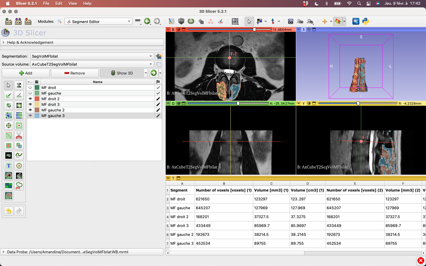
I want to know the area of the green surface on this image for example, according to an axis that I have chosen (fiducial node), and that would take into account all the pixels islands (including isolated ones).
In your image, the green areas are all connected, none is isolated.
“What is fat and what is muscle in your pictures ?”
In the first image of my previous post, red and brown correspond to fat, yellow and blue to muscle.
“Do you want sections of muscle without fat and fat without muscle?”
I especially want to be able to calculate the area of fat and the area of muscle separately in a chosen axial plane, whether they are visualized together or separately on my model (on the image here, only the fat is visualized).
If you move the Fiducial point in the selected slice view with the same slice orientation, the result should not change.
If you move the Fiducial point in another slice view or in the 3D view, the result will be different.
If you change the selected slice view’s orientation, the result will change also.
The cutting plane corresponding to the selected slice view’s orientation. The plane is constructed at the Fiducial point’s coordinates.
As a helper, the selected slice view’s orientation is memorised with the fiducial point the first time you click on it. This allows to restore the orientation when you click on it again. It is very helpful when working with diseased blood vessels with more than 1 control point.
The location of the Fiducial point is not memorised, it does not makes sense.
To reset the memorised orientation, choose More/Reset control point orientation and click on the Fiducial point again.
A connected or disconnected segment is the same if you uncheck ‘Limit to closest islands’. It does make a difference if this option is checked.
Hi. I need help for a issue I’m experiencing abou this module.
I am using segment cross section area tool to measure muscle mass volume at L3 vertebra corpus level. Sometimes the result shows zero. I couldn’t figure out why.
Do you see any error in the application log?
Can you share anonymized data or instructions to reproduce the issue using openly available data (such as images in the Sample data module)?