Once the DRR image is generated, you can transform DRR image into UnsignedChar scalar volume, using “Cast Scalar Volume” module. Newly created casted volume can be saved as PNG, JPEG or any other format.
Got it, thank you! I was asking because using DRR command in the “Plastimatch Command Prompt” on a PC yields a .pfm and a .txt file that contains the projection matrix that Andras mentioned in his last post.

I would like to figure out a workflow that is primarily within 3D Slicer, so I am trying to figure out the best way to obtain this projection matrix through 3D Slicer. I thought that outputting a .pfm or .pgm from the DRR Generation module might create a file on my local hard drive with the accompanying .txt.
Plastimatch projection matrix file format. Projection matrix description. DRR parameters description.
Can I obtain the Plastimatch DRR projection matrix from the DRR Generation module in 3D Slicer?
It’s impossible in current version, but such feature can be added into DrrImageComputationLogic of the module, or a function can be added to calculate projection of a markup point on the DRR image plane.
Can I access any of the Plastimatch command prompt capabilities through the Python terminal available in 3D Slicer? For example, “Plastimatch drr” or “Plastimatch convert”.
Right now I am alternating between 3D Slicer and the Plastimatch command prompt to label points on a CT and then create a DRR from the same CT. Just trying to figure out if there are any efficiencies to be had without getting in over my head coding.
Thanks again for your help on this!
No. You can’t. Plastimatch convert command doesn’t have implementation as a 3D Slicer module.
If you need calculate the projection of point by ray casting. simple intersection between a line (Point-1 is a x-ray source. Point-2 is your point ) and imager plane, it can be added to DRR calculation logic within a several days. You can set a fiducial point within CT data, and calculate point “projection” on DRR image using 3D Slicer python console.
Unfortunately, editing the DRR calculation logic is beyond my programming abilities. My workaround is to place points in 3D Slicer, then to create the DRR with the Plastimatch Command Prompt and pull the projection matrix from the .txt that is generated.
I have another question regarding the DRR Generation module: does the DRR calculation logic replicate the divergence of x-ray beams away from the source? I would like to simulate the size and shape distortions that are characteristic of computed radiography and digital radiography (ex. femoral heads appear non-overlapping in a lateral DR because of the cone-shaped of the beam).
So you need only a projection matrix, not the coordinates of projected points? You don’t need to change anything in logic, but after update you can calculate projection of the points on image plane, either in GUI or in 3D Slicer python shell, using a simple script.
Plastimatch simulates beam divergence (x-ray source to isocenter distance can be set in the “Beams” module). It’s not a parallel geometry, then x-ray comes from infinity.
That’s a fair point–my previous post didn’t capture my full workflow. I am actually just copying the projection matrix and RAS points into an Excel template that I created, which outputs the pixel coordinates. It’d be great to skip that altogether, but I am okay with the manual labor.
I see the controls for SAD/SID

Are there any process parameters that influence beam divergence?

Is there any documentation of the beam divergence from Plastimatch?
Thanks again for all of your help. I appreciate the prompt replies on a Saturday.
Currently, only some platimatch features are exposed in SlicerRT, but with very little work you can make anything available. You can either:
- bundle an executable and call it with a Slicer Python scripted module (as it is done in SlicerElastix, SlicerANTs, SegmentMesher extension), or
- you can add a Slicer CLI module to wrap library functions (as it is done already for 10 Plastimatch tools - PlmDrr, PlmLandwarp, PlmRegister, …), or
- you can expose Plastimatch library functions in PlastimatchPy
You should be able to find lots of description of this basic projection geometry on the web, and probably even in the DICOM or other standards. Source to image distance specifies one side of the right-angled triangle, and half detector size (= number of pixels * size of one pixel / 2) is the other side.
Did you try the “DRR Image Computation” module from “Radiotherapy” category? You have to create a RtPlan and a RtBeam nodes beforehard in the “External Beam Planning” and “Beams” modules respectively.
The “DRR Image Computation” module has better GUI, shows size and orientation of your imager, and shows plastimatch drr command parameters in the “Plastimatch DRR command arguments” subwindow.
Hi Mik,
The GUI for the DRR Image Computation module is fantastic. Would have saved me hours of fiddling with nrm and vup in the Plastimatch Command prompt and the DRR generation module.
That being said, I need a .png of the DRR and the pixel coordinates of reference points that I placed on the source CT. As far as I can tell, those are not available from any of the modules in 3D Slicer.
Does the 3D Slicer support team ever engage in paid consulting to enhance existing modules to meet unique user needs? Apologies if this is outside of the rules of the forum.
Andrew
Maybe someone will contact you in a private message offering paid help, and you can also post your asking for help in the Jobs - 3D Slicer Community category or contact any of the Slicer Commercial Partners.
I can do the calculation of markups projections on a imager plane. I need such soft of functionality for myself. Do you need projection coordinates in World or in local imager system (offset from imager origin position (0,0) or column,row position)?
That would be great! I would like to have the pixel coordinates relative to the top left corner of the PNG of the DRR. Right now, I am using an Excel template to calculate the coordinates relative to the isocenter selected in 3D Slicer. See workflow below. I am using GIMP to convert the .pfm produced by Plastimatch into a .png.

As a side note, you can see that the contrast in the resulting DRR is suboptimal. I posted a question about this in a separate thread, but haven’t tried the “Plastimatch adjust” functionality yet.
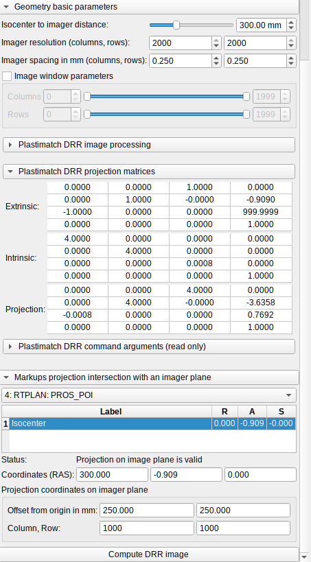
Here is an upgrade for DRR Image Compulation i suggest to add to SlicerRT.
- Plastimatch DRR projection matrices. Self explanatory, matrices are the same as plastimatch output, for checking and debugging.
- Markups projection intersection with an imager plane:
Select markups node. Select control point. If point is within volume bounds and if there is a intersection with an imager plane you will get as a result: coordinates of perspective projection in RAS (World): offset from imager origin in mm within imager coordinate system, pixel position (Column, Row) of projected control point.
PR is on the way.
Can download the latest release, and install SlicerRT once again? The updated DRR Image Computation module with perspective projection of markups on imager plane has been compiled and ready for your testing.
How to test:
- Load a CT volume;
- Create a RTPlan node with proper isocenter;
- Create RTBeam node with proper orientation angles: gantry, couch;
- Created a fiducial markups node within the CT volume, with a required number of control points;
- Select volume and beam in
DRR Image Computiation, select a created markups node inMarkups projection intersectionframe, and finally select a desired control point. - Check the calculated coordinates for correctness.