I’m hoping someone can help with a workflow to import an STL file into Slicer, convert it to a series of DICOM files and export those DICOM files. I’ve checked other forums and can’t find anything that gives a step-by-step of the process. Thank you in advance for the help!
Not necessarily. I have a 3D model that I’ve saved in STL format that I need to generate DICOM file for. The DICOM files should be the same format as what is generated from a CT or MRI scan.
If I understand your needs correctly, given that you will need labelmaps anyway, you can skip the Meshmixer step and do that in Slicer as well. What I can imagine:
Do not export it to STL
No change
No change
Import SolidWorks STL into Slicer -> Convert it to segmentation node (if you want to make sure the labelmap geometry matches the CT, you can create empty segmentation in Segmentations module, change master to Closed surface, import STL part, and “advanced create” the labelmap specifying the CT as reference volume) -> Change master to Binary labelmap -> Import “patient 3D volume” that you mention in step 2 (whatever it means…) in this segmentation node -> In Segment Editor, use the Logical operators to unify the part and the “patient volume”
Not needed
In Segmentations module, Export segmentation to labelmap, specifying the CT as reference volume (in Advanced section of Import/Export) -> In Volumes module, change the volume type from labelmap to scalar volume -> In Data module, drag&drop it in the same study as the CT -> Right-click it, Export to DICOM
My only comment would be that @aleesdesigner probably needs to design something around the patient’s bone/tissue geometry so would need to export the file at step 2 in order to load it into Solidworks.
If I am interpreting your need correctly, my suggestion would be:
Import DICOM data from a patient CT scan into Slicer.
Export patient 3D volume to STL file.
Import patient STL into Solidworks and create a 3D component in SolidWorks WITHOUT moving the location of the patient STL file in 3D space in Solidworks.
Export 3D component from SolidWorks to STL file.
Import the 3D component STL from Solidworks into Slicer. As long as you have not changed the coordinate system in Solidworks then it should appear in exactly the right place on the patient’s bone/tissue in slicer.
Go to Segmentations module (not segment editor). Select the segmentation node which you used to originally segment the patient’s bone/tissue. Go to Import/Export models and labelmaps area and import the model into the segmentation node.
Go to segment editor, click on you original patient bone/tissue segment and then click the logical operators effect. Select Add and add the solidworks model segment to the original segment. (Instead of using meshmixer)
Go back to the segmentations module, click on the newly combined segment and using the same Import/Export area export the segment as a label map.
Go to the volumes module and convert the new label map to a scalar volume.
Go to data module and right click on the new volume and select export to DICOM.
Open and review DICOM files in a piece of equipment designed to open and review standard CT/MRI scan DICOM files.
Note that the dicom file is just a completely black and white image. All the bone contrast is lost. You might have to do something a bit more fancy to combine your model volume on top of the original volume if you still want the original bone contrast but I am pretty sure it would be possible.
I tried this out and it worked well for me. Thanks to @cpinter for the extra tips about converting back to a scalar volume etc.
Hi there. My use case for Slicer is similar, but with a key difference: I need to import an STL surface mesh of a physical object (either from an optical scanner or a CAD design) and then export it as a stack of DICOM images representing cross-sectional slices of the surface contours.
So far, I have successfully opened my STL file as a “model,” but I am unable to visualize any slice images from it. (Importing the same data as a “segmentation” does not display any object information.) This STL was not generated by SolidWorks.
What specific characteristics does the STL file require for this to work? I am exploring alternative software options, but I would first like to determine if Slicer can accomplish this task—specifically, exporting the 3D object as a stack of 2D DICOM images.
Great, this works good. Unfortunately on Blender I safe the object file very tiny. Can I ajust the scene in 3D Slicer? The section images on default only alow me three steps: -1, 0, 1 mm. I would love to refine these steps.
I would appreciate, if zooming into the 3D volume would adjust the three predefined section images… This might not be the case, this I only recognize green dots in the center. How can I zoom into the section images?
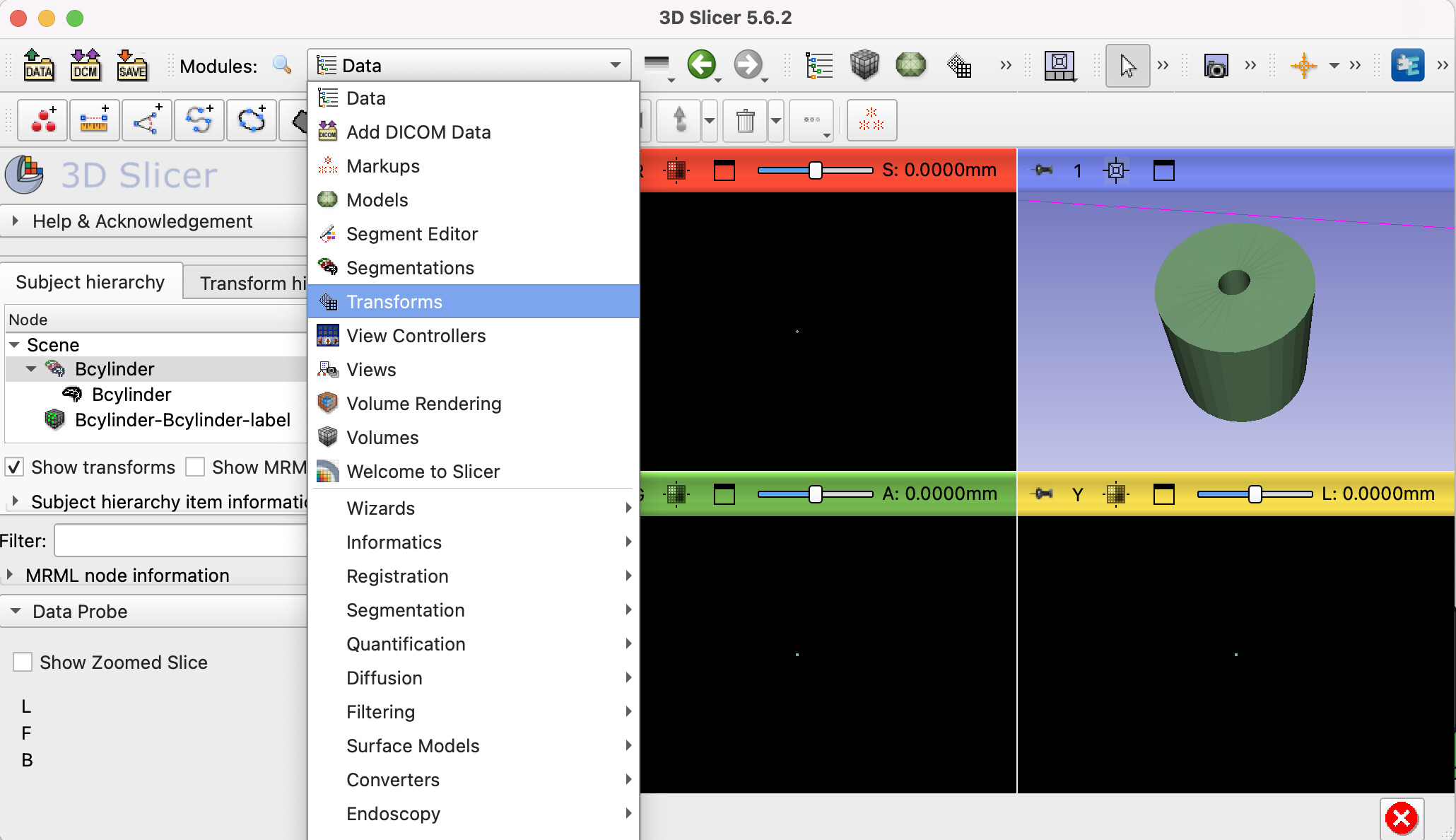
Slicer assumes the unit in your STL are millimeters, since mm is its default unit and STL does not have a way to tell Slicer what those units are. You can use the transforms module to scale your model up/down and then you can do the conversions again.
Thank you very much for your attention. I checked the Tranforms Model and attach some outcome. Still, I am on the wrong way. Could you help me out, please? I still believe Slicer is my option on this task. Best regard, Verena
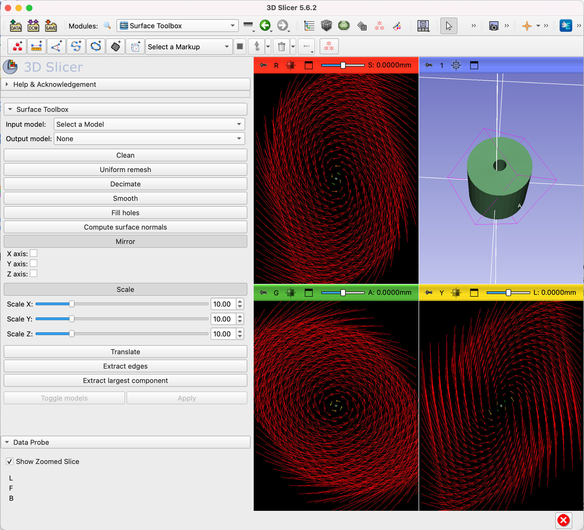
Actually just use the Scale Model option of the Surface Toolbox module and increase the scale on XYZ and up to the maximum. Then check the resultant model, if it is sufficiently large, then proceed with conversion. If not, apply the scaling again.
Note that you are now arbitrarily scaling things, not sure if this is compatible with your end goal.
Hi Murat, thank you for your attention. Scaling sounds great, yet I am not sure how to “apply“ your idea. I found the corresponding toolbox, as atteched in the screenshots. However, I have no clue hoy to perform the scalinging. Can you help me out, please?
My end goal is to collect section images of this 3D object (hollow cylinder), where the surface projects as concentric circles. I am looking forward to compare these image stack with a CT tomography (DICOM image stack) and possibly use some design imformation on the iterative reconstruction task. The real cylinder is a metal one and causes beam hardening.
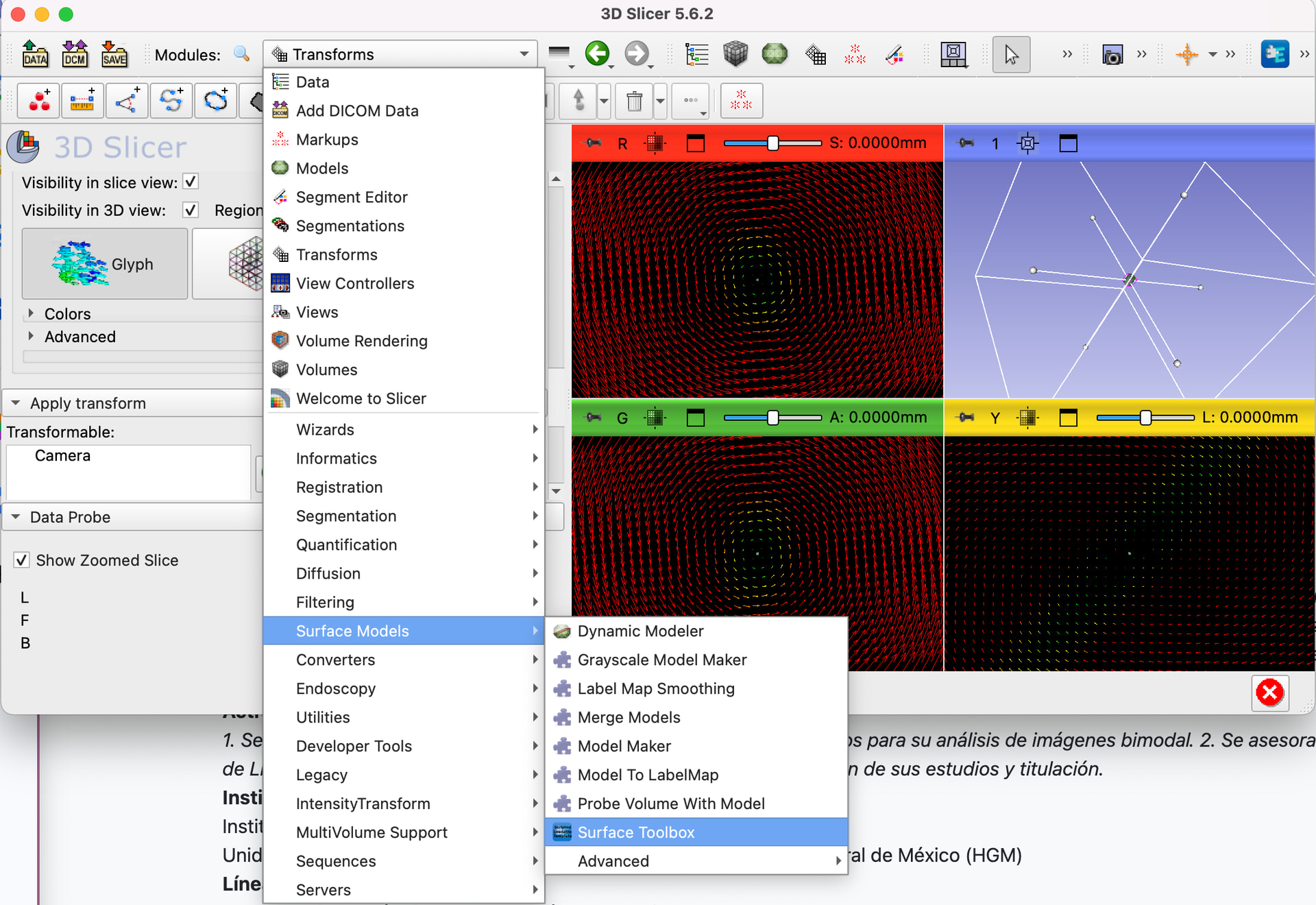
to accomplish what you need to do, you need to get familiar with Slicer’s UI and how these types of modules are set to work. I think you should begin with Slicer’s official documentation
and then specifically see the section on Surface Toolbox.