Programmatically Create a SegmentationNode and LabelMapNode from Polygon Coordinates

Operating system: Windows 10
Slicer version: 4.10.2

Hello,

I have some manually drawn ROIs represented as points in the row, column, slice coordinate frame. I am trying to programmatically generate a vtkMRMLSegmentationNode from those points. I also want to be able to export a image that is 1 everywhere inside the polygon and 0 outside. Right now, the approach I am taking is as follows, with actual code below

  1. Turn the polygon coordinates (row, column, slice) into a binary numpy array that equals to 1 inside the polygon and zero everywhere else.
  2. Take the binary numpy array and put it into a vtkMRMLLabelMapVolumeNode
  3. Import that LabelMapNode into a vtkMRMLSegmentationNode
  4. Save the segmentation node as an RTStruct (not shown in the code because I’m doing it manually)

The problem I am having is with step 1 above. Although scikit-image and PIL have great functions to help convert polygon points into a binary map (e.g. skimage.draw.polygon) I cannot successfully install scikit-image or PIL into the Python interpreter. The rest of the steps 2-4 work fine, as verified by manually creating a box mask using numpy array slicing.

Does slicer already have a function that can convert a polygon to a binary mask? Or, alternatively, can I just somehow directly load the polygon coordinates into a segmentation node? The polygons are 3D (i.e. they span multiple rows, columns, slices).

Here is the relevant portions of my code:

#function createSegNode creates a segmentation node from a mask and name
#inputs
#mask: a 3D numpy array with 1s everywhere inside the polygons and 0s elsewhere
#name: name to assign new segmentation node
def createSegNode(mask,name):

#create volume node representing a labelmap
volumeNode = slicer.mrmlScene.AddNewNodeByClass('vtkMRMLLabelMapVolumeNode')
volumeNode.CreateDefaultDisplayNodes()

#place np array in volume node
updateVolumeFromArray(volumeNode, mask.astype(int))

#orient the labelmap in the right direction
volumeNode.SetOrigin(im_node.GetOrigin())
volumeNode.SetSpacing(im_node.GetSpacing())
imageDirections = [[1,0,0], [0,-1,0], [0,0,-1]]
volumeNode.SetIJKToRASDirections(imageDirections)

#convert labelmap into a segmentation object
segNode = slicer.mrmlScene.AddNewNodeByClass('vtkMRMLSegmentationNode')
slicer.modules.segmentations.logic().ImportLabelmapToSegmentationNode(volumeNode, segNode)
segNode.SetName(name)

#create a toy 2d polygon mask
r = [100, 150, 150, 100] #polygon rows
c= [100, 100, 150, 150] #polygon columns
m2=np.zeros((2,len(r)))
polygon_array = create_polygon([512,512], m2.T).T #I don’t have a good function to do this reliably. Right now I’m using a function I found on stackoverflow that doesn’t accurately reproduce the polygons

#put the polygon into a 3d array
im_node=getNode(“<< node name>>”)
node_np=slicer.util.arrayFromVolume(im_node)
polygon_array_3d=np.zeros(node_np.shape)
polygon_array_3d[20,200:250,200:250]=1
createSegNode(seg_d,seg) #calls above function
It is very difficult to do this robustly. Naive implementation in scikit-image and PIL work for simple cases and maybe yours is like that, so that’s one approach you can try. You can only install non-native Python binary packages in recent Slicer Preview versions, not in Slicer-4.10.x.

Yes, you can. Segmentations module can accept various representations, including “planar contours”, which is how your data is represented now. Then, segmentations module can automatically convert this to various other representations, such as binary labelmap or closed surface. The converter to binary labelmap is much more sophisticated than the simple one in scikit-image - it can can handle handle keyholes, branching, contours at non-equal distances, etc.

What you need to do is to save your contours a VTK polydata and add some custom fields that indicate that the polydata should be interpreted as a segmentation node. See complete example here.

Closed surface representation is provided by SlicerRT extension (as planar contours are commonly used representation in radiation therapy), so you need to install this extension for this representation to show up in Slicer.

Hello,
Thanks for the help. This points me in the right direction but I’m relatively new to VTK so I hope I can ask a few follow-ups.

  1. If I understand correctly, I need to save the contour points (e.g. rows, columns, slices) to a .vtk polyData file on my hard drive using a function like vtkToPoly here.
  2. While saving the .vtk file, I need to set a custom field as so: Segmentation_ContainedRepresentationNames = “Planar contours”
  3. Use the function vtkMRMLSegmentationStorageNode.ReadPolyDataRepresentation() to open the .vtk file as a segmentation node.

If that is correct, then my main question is how to save a .vtk file from the slicer python interpreter? I think I can’t install the evtk.hl module linked above from the windows slicer python interpreter.

Thanks a lot for your help.

Ryan

Probably the simplest is to create a segmentation node directly instead of creating a vtk file that can be loaded as segmentation. Here is a complete example of creating a segment (including closed surface and binary labelmap representation) from a list of contour points:

# Create segmentation node where we will store segments
segmentationNode = slicer.mrmlScene.AddNewNodeByClass("vtkMRMLSegmentationNode")
segmentationNode.CreateDefaultDisplayNodes()

# Create a segment from planar contours - can be repeated for multiple segments

segmentName = "test"
segmentColor = [1, 0, 0]
contours = [
    [[10,10,0], [30,10,0], [30,40,0], [10,25,0]],
    [[12,13,10], [31,9,10], [34,41,10], [12,23,10]],
    [[14,8,20], [22,11,20], [28,16,20], [16,28,20], [2,21,20]],
]

contoursPolyData = vtk.vtkPolyData()
contourPoints = vtk.vtkPoints()
contourLines = vtk.vtkCellArray()
contoursPolyData.SetLines(contourLines)
contoursPolyData.SetPoints(contourPoints)
for contour in contours:
    startPointIndex = contourPoints.GetNumberOfPoints()
    contourLine = vtk.vtkPolyLine()
    linePointIds = contourLine.GetPointIds()
    for point in contour:
        linePointIds.InsertNextId(contourPoints.InsertNextPoint(point))
    linePointIds.InsertNextId(startPointIndex) # make the contour line closed
    contourLines.InsertNextCell(contourLine)

segment = slicer.vtkSegment()
segment.SetName(segmentName)
segment.SetColor(segmentColor)
segment.AddRepresentation('Planar contour', contoursPolyData)
segmentationNode.GetSegmentation().AddSegment(segment)

Hi Andras,
Thanks so much for the help, I am so close but there is a remaining issue. I expected that when I view the segmentationNode overlaid on my image, the coordinates of the segment should match the numerical values that I loaded into the segmentationNode object. But they don’t.

I searched a lot of documentation and found the SetReferenceImageGeometryParameterFromVolumeNode() function for vtkMRMLSegmentationNode but this didn’t seem to help. I also tried converting the segmentationNode to a binary labelmap, then applying the origin, pixel spacing, and image direction of my image to the labelmap, but still the location of the labelmap didn’t match the value of the contour points that I loaded in.

Here is the relevant code:

#createSegNode2 function from Andras Lasso
def createSegNode2(segmentationNode,contours,name):
    # set up contour objects
    contoursPolyData = vtk.vtkPolyData()
    contourPoints = vtk.vtkPoints()
    contourLines = vtk.vtkCellArray()
    contoursPolyData.SetLines(contourLines)
    contoursPolyData.SetPoints(contourPoints)

    for contour in contours:
	    startPointIndex = contourPoints.GetNumberOfPoints()
        contourLine = vtk.vtkPolyLine()
    	linePointIds = contourLine.GetPointIds()
       	for point in contour:
	    	linePointIds.InsertNextId(contourPoints.InsertNextPoint(point))
	    linePointIds.InsertNextId(startPointIndex) # make the contour line closed
    	contourLines.InsertNextCell(contourLine)

    segment = slicer.vtkSegment()
    segment.SetName(name)
    #segment.SetColor(segmentColor)
    segment.AddRepresentation('Planar contour', contoursPolyData)
    segmentationNode.GetSegmentation().AddSegment(segment)

#load the volume node corresponding to CT image
im_node=getNode("1006: UNKNOWN")

#Create segmentation node where we will store segments
segmentationNode = slicer.mrmlScene.AddNewNodeByClass("vtkMRMLSegmentationNode")
segmentationNode.CreateDefaultDisplayNodes()
segmentationNode.SetReferenceImageGeometryParameterFromVolumeNode(im_node) #I tried with and without this line

contours = [
[[10,10,0], [30,10,0], [30,40,0], [10,25,0]],
[[12,13,10], [31,9,10], [34,41,10], [12,23,10]],
[[14,8,20], [22,11,20], [28,16,20], [16,28,20], [2,21,20]],
]

createSegNode2(segmentationNode,contours,'test')

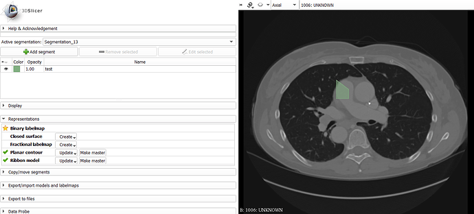
Here is the segment (green) on top of my image

The pixel location of the bottom left corner of the green segment according to the data probe is (299,241,30) not even close to the values stored in the contour variable above. How can I match the coordinate system of the segmentation node to the coordinate system of the image?

Thanks again for your help
Ryan

1 Like

What software did you use to draw the contours?

What coordinate system the numbers are stored in? Most common are LPS, IJK, and RAS (Slicer uses this).

Do you have an example data set that you can share?

Ryan, were you able to solve this issue? I am having same issue – my segmentation-polygon are not appearing in expected location in the 2D view, although I am using (y,x,slicecount) format, and coordinates seem to look okay (in text logs)

If you have any mismatch in coordinates then probably you just did not get the IJK to RAS transformatin right. If you provide an example data set then we can tell you how to do compute and apply the transform correctly.

Andras, is there an example code-snippet for IJK to RAS transformation?

There are several examples for that in the script repository, e.g., this.

1 Like

perfect! Thank you, you saved my day.

1 Like

Hi Gaurav,
Yes, Andras was correct in that I was working in IJK, not physical coordinates. Once I switched to physical, then the contours imported correctly.

Ryan

1 Like