Hello,
First of all, thank you again for creating Slicer, it really helps my research a lot.
I have the following problem/ question. I am trying to import a 3D-Skeleton.tif (created in ImageJ, width of the skeleton structure is 1 voxel) in Slicer and export an STL model.
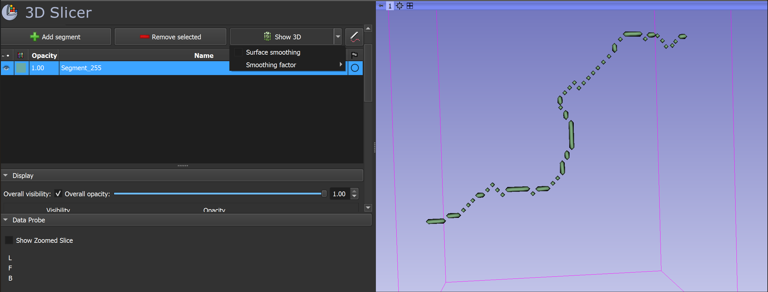
I execute the following steps: 1. Import the .tif file in Slicer as LabelMap 2. “Convert LabelMap to Segmentation Node” 3. Open “Segment Editor” Module 4. “Show 3D” with “Surface Smoothing” turned off → the result can be seen in Screenshot 1.
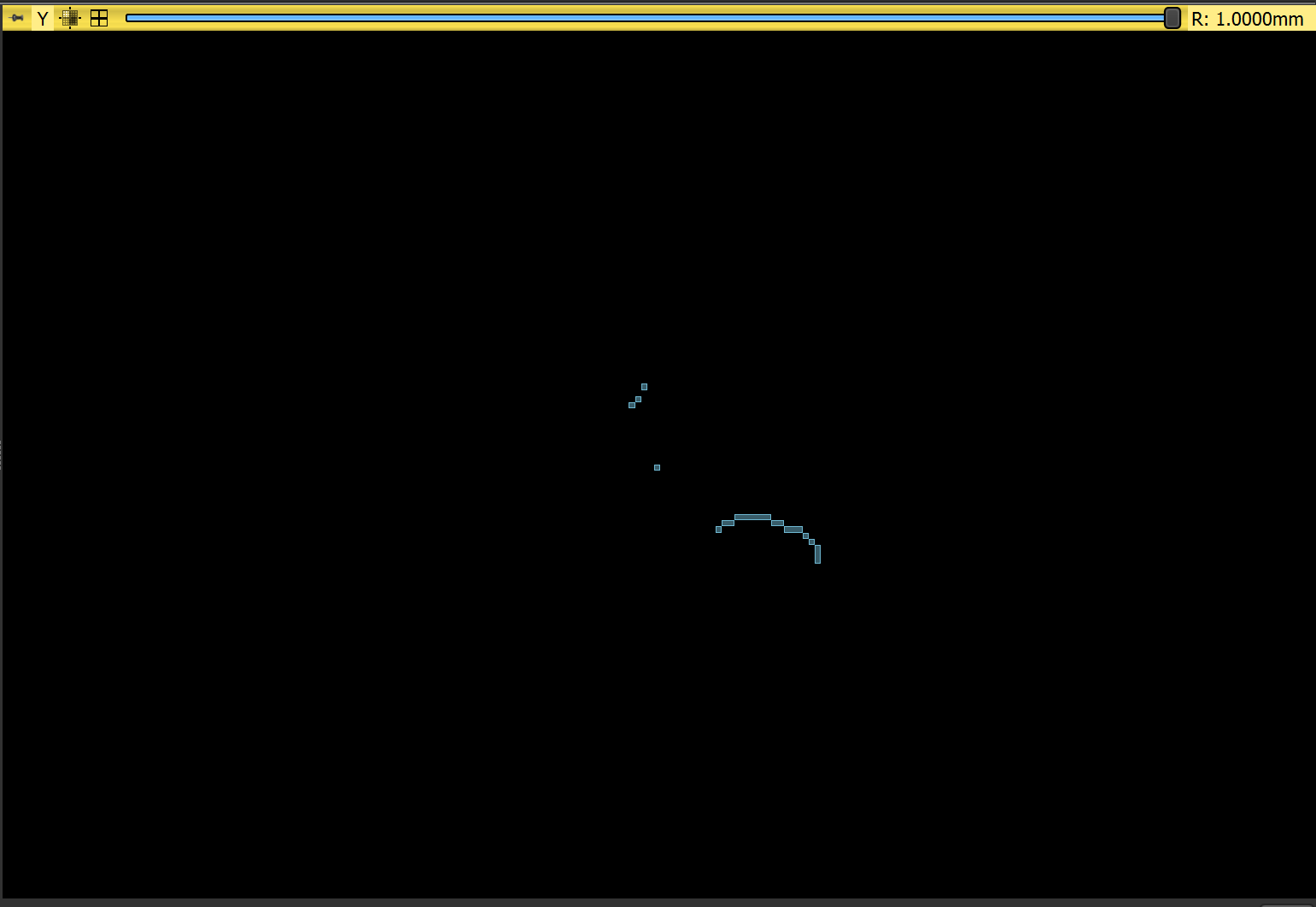
My question is, why do the voxels of the Skeleton get displayed by Slicer as rhomboids or rotated cubes with reduced size? This causes the structure to look like there are holes in it. If you look at Screenshot 1, next to Slicer’s visualisation I have uploaded the ImageJ 3D visualisation. ImageJ displays the voxels as unrotated cubes and where the structure goes in an oblique direction, the adjacent voxels touch each other at their edges. Slicer’s visualisation at those areas leaves empty space beetween adjacent voxels. Can this be changed in Slicer’s settings?
N.B in Screenshot 2 there is Slicer’s visualisation in a sagittal slice. The voxels are unrotated cubes, like ImageJ displays them in its 3D-View, the edges touching when the structure is oblique.
Thank you for the idea, Surface smoothing for Show 3D was turned off before I took the screenshots (it was unticked like in your screenshot, I also mentioned that in my post). In fact when there is any Surface smoothing on the 3D Image, it dissapears (I guess because it is only 1 Voxel wide).
Update: I opened my .tif file in ImageJ and saved it as an .nrrd file. Then I imported it in Slicer as a Volume and went “Volume Rendering” → Display Volume (ticked the eye-icon next to the volume). This way I get the result I expect (s. Screenshot 3), however now I can’t export it to STL.
When I try to create a Segmentation from that in order to save it as STL, I get the same result as in Screenshot 1 with the rhomboid voxels.
N.B Interestingly, going out from the wanted Representation of the Volume in Screenshot 3, when I increase the “Shift” Parameter under “Display” in “Volume Rendering” (s. Screenshot 4), I get similar rhomboid voxels as in the Segmentation 3D-View. Is there a way to adjust the same “Shift” Parameter of the Segmentation? (I couldn’t find it)
However, I would recommend to use VMTK extension for extraction and analysis of vessel centerlines. It will simplify your workflow and provide better results. You can probably even do all your analysis within Slicer - basic quantifications are already available via GUI and you can run any additional custom analysis using Python scripting.
What I am trying to visualise is a skeleton of a segmentation of a suture, so it is not a blood vessel, the VMTK extension would have been very useful otherwise.
Unfortunately the problem I experience (the skeleton being displayed with rhomboid voxels and holes when loaded as segmentation, s. Screenshot 1 from my first post) still persists when I use the method you describe (s. Screenshot 5 below). I had disabled Surface smoothing for Screenshot 1 as well.
However I am starting to think that a surface can’t be displayed otherwise (s. Screenshot 6 from ImageJ when you create a 3D Surface of the same Skeleton → it still has rhomboid voxels and slight holes between adjacent voxels)?
Screenshot 6: same Skeleton.nrrd loaded as Surface in ImageJ and exported as STL (notice ImageJ also uses rhomboid voxels when it creates a Surface + holes between adjacent voxels)
The original developers of VMTK used it mainly for vascular applications, but it is equally applicable for analysis of any somewhat elongated, tubular-like structures (has been used successfully for airways, intestines, plant roots, etc.). It should work well for sutures, too.
Yes, you are right, you won’t be able to see cube voxels. It is because segmentation is for representing smooth, continuous surfaces. Even if in some representations (such as in binary labelmap) discrete point samples are used, the result is always reconstructed into a smooth surface. For binary labelmap to closed surface conversion we use continuous version of the flying edges algorithm, which creates rhomboids from standalone voxels (and not the discrete version, which creates cubes).
You could run the discrete version manually by using a couple of lines of Python script, but I would not recommend that, because physical reality is never discrete (at least not in our domain). Instead, properly segment the real size of the suture, and then get the smooth continuous centerline curve directly from that, using VMTK.
If you don’t have the original segmentation anymore, just the binary labelmap skeleton then you can use Margin effect in Segment Editor to blow it up into a thicker tube. You can then use VMTK on this thicker segment.