Sorry there has been an API change since this snippet was written. Try this, seems to work for me using the sample data provided in Slicer 5.6.1
import numpy
scene = slicer.mrmlScene
F = getNodesByClass('vtkMRMLMarkupsFiducialNode')
F = F[0]
# Get the fiducial IDs of porions and zygomatico - orbitale suture from the fiducial list by name
po1_id = -1; po2_id = -1; zyo_id = -1;
for i in range(0, F.GetNumberOfControlPoints()):
if F.GetNthControlPointLabel(i) == 'poR' :
po1_id = i
if F.GetNthControlPointLabel(i) == 'poL' :
po2_id = i
if F.GetNthControlPointLabel(i) == 'zyoL' :
zyo_id = i
# Get the coordinates of landmarks
po1 = [0, 0, 0]
po2 = [0, 0, 0]
zyo = [0, 0, 0]
F.GetNthControlPointPosition(po1_id,po1)
F.GetNthControlPointPosition(po2_id,po2)
F.GetNthControlPointPosition(zyo_id,zyo)
# The vector between two porions that we will align to LR axis by calculating the yaw angle
po =[po1[0] - po2[0], po1[1] -po2[1], po1[2]-po2[2]]
vTransform = vtk.vtkTransform()
vTransform.RotateZ(-numpy.arctan2(po[1], po[0])*180/numpy.pi)
transform.SetMatrixTransformToParent(vTransform.GetMatrix())
# Apply the transform to the fiducials and the volume
transform = slicer.vtkMRMLLinearTransformNode()
scene.AddNode(transform)
transform.SetMatrixTransformToParent(vTransform.GetMatrix())
V = getNodesByClass('vtkMRMLScalarVolumeNode')
V = V[0]
V.SetAndObserveTransformNodeID(transform.GetID())
F.SetAndObserveTransformNodeID(transform.GetID())
# Get the updated (transformed) coordinates from the list
po1 = [0, 0, 0]
po2 = [0, 0, 0]
zyo = [0, 0, 0]
F.GetNthControlPointPosition(po1_id,po1)
F.GetNthControlPointPosition(po2_id,po2)
F.GetNthControlPointPosition(zyo_id,zyo)
# Apply the transform to the coordinates
po1 = vTransform.GetMatrix().MultiplyPoint([po1[0], po1[1], po1[2], 0])
po2 = vTransform.GetMatrix().MultiplyPoint([po2[0], po2[1], po2[2], 0])
zyo = vTransform.GetMatrix().MultiplyPoint([zyo[0], zyo[1], zyo[2], 0])
po =[po1[0]-po2[0], po1[1]-po2[1], po1[2]-po2[2]]
# Calculate the rotation for the roll
vTransform2 = vtk.vtkTransform()
vTransform2.RotateY(numpy.arctan2(po[2], po[0])*180/numpy.pi)
# Apply the transform to previous transform hierarchy
transform2 = slicer.vtkMRMLLinearTransformNode()
scene.AddNode(transform2)
transform2.SetMatrixTransformToParent(vTransform2.GetMatrix())
transform.SetAndObserveTransformNodeID(transform2.GetID())
# Get the coordinates again
po1 = [0, 0, 0]
po2 = [0, 0, 0]
zyo = [0, 0, 0]
F.GetNthControlPointPosition(po1_id,po1)
F.GetNthControlPointPosition(po2_id,po2)
F.GetNthControlPointPosition(zyo_id,zyo)
# Apply transforms to points to get updated coordinates
po1 = vTransform.GetMatrix().MultiplyPoint([po1[0], po1[1], po1[2], 0])
po2 = vTransform.GetMatrix().MultiplyPoint([po2[0], po2[1], po2[2], 0])
zyo = vTransform.GetMatrix().MultiplyPoint([zyo[0], zyo[1], zyo[2], 0])
po1 = vTransform2.GetMatrix().MultiplyPoint([po1[0], po1[1], po1[2], 0])
po2 = vTransform2.GetMatrix().MultiplyPoint([po2[0], po2[1], po2[2], 0])
zyo = vTransform2.GetMatrix().MultiplyPoint([zyo[0], zyo[1], zyo[2], 0])
# The vector for pitch angle
po_zyo = [zyo[0]-(po1[0]+po2[0])/2, zyo[1]-(po1[1]+po2[1])/2, zyo[2]-(po1[2]+po2[2])/2]
# Calculate the transform for aligning pitch
vTransform3 = vtk.vtkTransform()
vTransform3.RotateX(-numpy.arctan2(po_zyo[2], po_zyo[1])*180/numpy.pi)
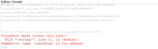
# Apply the transform to both fiducial list and the volume
transform3 = slicer.vtkMRMLLinearTransformNode()
scene.AddNode(transform3)
transform3.SetMatrixTransformToParent(vTransform3.GetMatrix())
transform2.SetAndObserveTransformNodeID(transform3.GetID())
slicer.vtkSlicerTransformLogic().hardenTransform(V)