I would like to report a problem which occurs when I convert my stl model to segmentation node in 3D slicer.
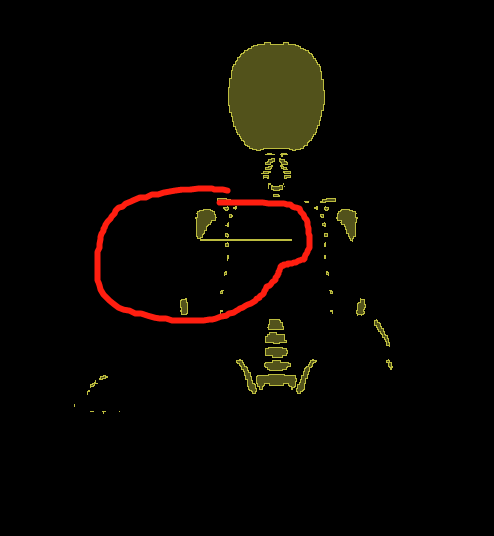
Basically, what I have is a stl model, as shown in figure1.
I tried with version 4.10, 5.02, and 5.22. All of them has this problem.
Does anyone also meet the similar problem before? I suspect there’s a bug in 3D Slicer.
Welcome any kinds of discussion in advance!
This kind of issue can happen when there are small triangles or other issues. You can try increasing the resolution of the segmentation grid or slightly rotating and hardening the model before converting.
Thanks, I have two follow-up questions. I tried to change the spacing here. But I am not sure which one I should change: the stl geo file or the segmentation node file after conversion?
I tried both, but unfortunately it didn’t solve my problem.
I manually changed the spacing of the STL from 1mm to 0.5mm.
Then I click ‘OK’, it showed one error ‘Source volume is not set as either the foreground or background’, and I got a blank output.
Then I changed the oversampling factor from 1 to 1.5, 2 for the segmentation node.
But in the output I can still see those additional bars…
Is my operation what you suggested? I am not sure if I did something wrong in this step.
Yes, you select the segmentation node and choose a higher resolution. You may still get artifacts due to degenerate triangles on the input. You may want to try different options in the SurfaceToolbox to clean up the mesh, or as I mentioned earlier it might help to slightly rotate the model with a transform (then harden it) and try rasterizing. You can also inspect the model in the area where the conversion artifacts are, e.g. by turning on the edge visibility to see what’s going on. In the worst case you might just manually clean up the artifacts with the segment editor.
The bars are due to the input mesh is not watertight (there are some open, non-manifold, or intersecting surfaces).
Even if the input surfaces are not watertight, if all the model/slice intersections on axial slices are closed then you may avoid the bars (that’s why @pieper suggested rotating your model). It may worth spending a little time with changing the orientation slightly, or by doing 90 degree rotations around various axes.
However, if that does not help then you need to either get watertight models or you can remove the bars manually in Segment Editor (e.g., using Scissors effect).