Operating system: Windows 10
Slicer version: the latest
Expected behavior: create a 3D model from DICOM images…that were created by converting jpgs into dicom
Actual behavior: Each dicom image got imported as if it were it’s own patient. So, 26 new patients with a series of 1 dicom image as opposed to 1 patient with a series of 26 dicom images. I need the later to make a 3 d image.
A lot depends on what tool you use to convert jpg to dicom.
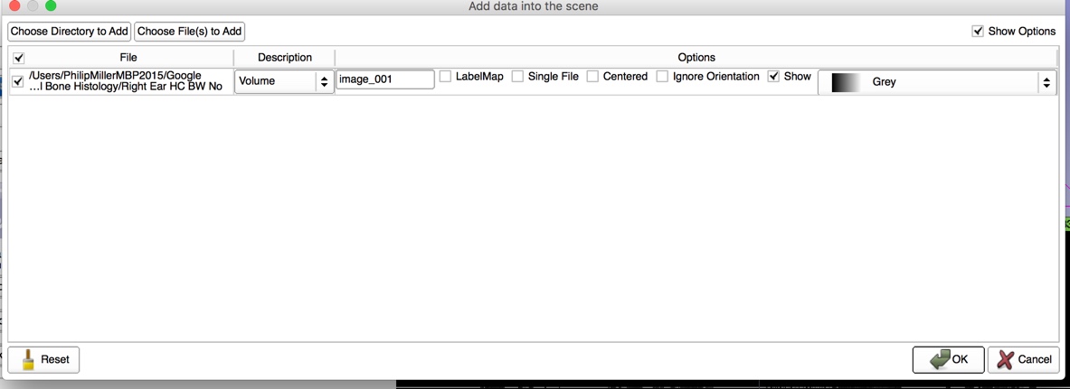
Probably better to try loading the jpg files directly:
Great. Let me try this


Choose only a single file of the sequence. You can find here a video as well:
That looked straight forward, but when I tried it, only one image of the 26 loaded. How do I get all of them to load?


see video here: https://www.screencast.com/t/eTowM5ypu7fX
And access to the files here:
https://drive.google.com/open?id=1XhaGbwnN34g8cRzSgk7mJnj7uTJlhjc8
I am very grateful for all of your assistance.
PJM
Hi Philip -
Thanks for sharing the data - I can see now the issue is that while the filenames are correct to form a volume, it turns out the files aren’t all the same sizes. The snippet from the error log below gives the details.
If you know that the files have consistent pixel sizes (acquired at the same scale) then you can crop or pad them all to the same dimensions and then the will load. From a quick look it’s not clear to me how well they will align in 3D and if there’s enough out of plane resolution to make a good 3D model.
Description: ImageIO returns IO region that does not fully contain the requested regionRequested region: ImageRegion (0x7ffeefbfc630)
  Dimension: 3
  Index: [0, 0, 0]
  Size: [5672, 3373, 1]
StreamableRegion region: ImageRegion (0x7ffeefbfc668)
  Dimension: 3
  Index: [0, 0, 0]
  Size: [5520, 3548, 1]
There are lots of ways to manipulate your data with various scripts and applications. If you want a GUI application and have windows then Irfanview can be a handy tool as shown in this tutorial.
-Steve
I’ve also noticed that slices seem to be misaligned with each other (there is translation and rotation between neighbor slices). You would need to spatially register slices to each other before you can display it as a 3D volume. I think Fiji has such registration tools and it can also save the image stack as an .mha file that Slicer can load directly.
OK…can I just hire you??? !!
It should not be necessary! If this is a one-off case then I (or others who are more experienced in histology slice registration) can create a Slicer-compatible volume for you from the data set that you provided.
If you need to create volumes from slices regularly, then you need to come up with a processing workflow. Slice registration may be a critical point of the workflow, as it may be difficult to find matching points between slices and your sample may also deform while it is being sliced. For now probably your best bet is to either come up with a slicing and imaging protocol that provides aligned slices; or retrospectively align them in Fiji. Later, if you need highly optimized workflow, then probably you would want to have a slice stack registration available in Slicer, so that you can do everything in one software.
OK…so, I used the first one to get all images of the proper dimension, and then to invert the colors so I could keep white bone and black air. They imported correctly, but I think all as seperate volumes though they appear to be all linked and I can scorll through them. BUT, how do I get a volume rendering???
See video. https://www.screencast.com/t/vtBM0x1nk
Thanks for all of your assistance!
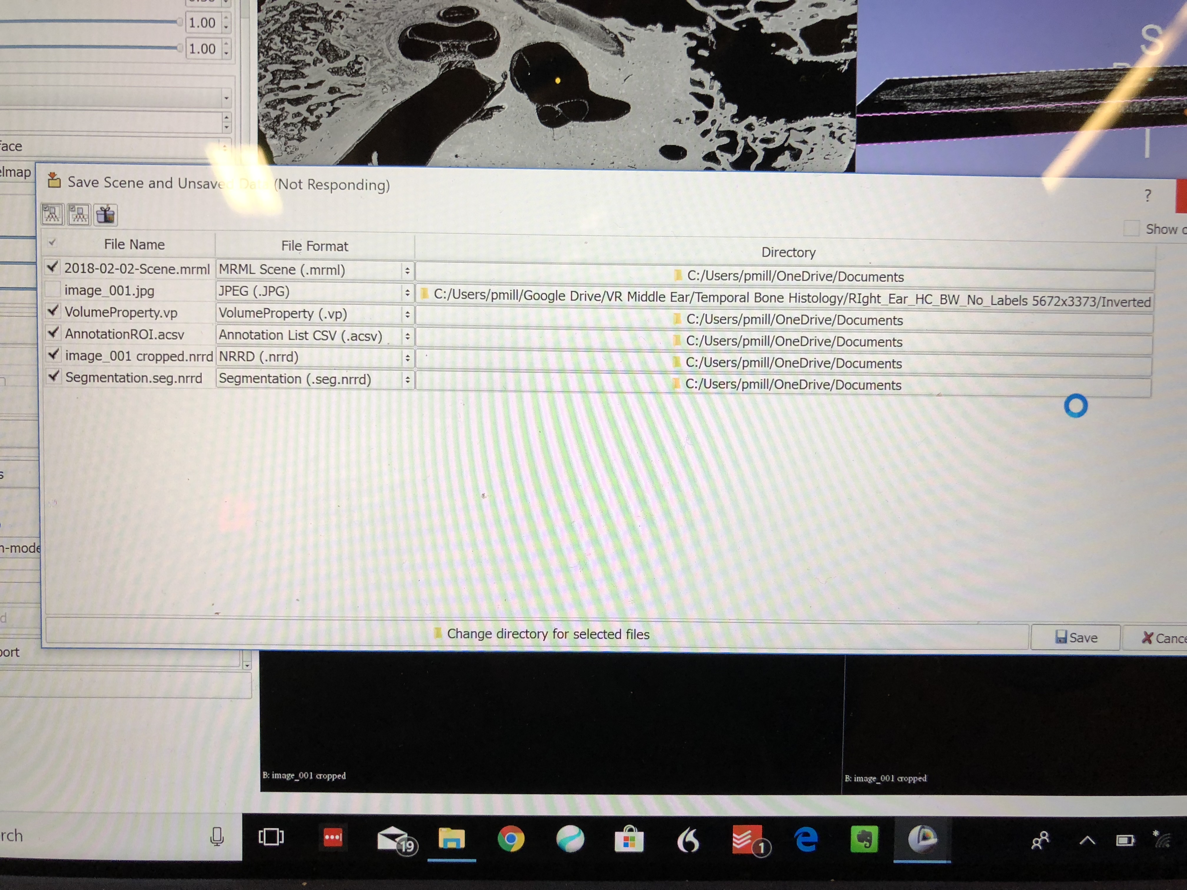
And…I saved them with this information…if it helps…
Go to volume rendering, select your volume, and click the eye icon to show the volume.
Probably the volume will look flat, as by default slice spacing is the same along all axes. To fix that, go to Volumes module, open Volume information section, and set the third value of Image spacing to the higher value (the value should be the same as the space between your image slices, in mm). For correct dimensions within the slice, set the first two values of Image spacing to the size of one pixel (in mm).

The right answer for the pixel spacing depends on how the images were acquired and that info is probably not recorded in the jpg files. Sometimes people include a ruler in the photo for reference and make a note of the spacing of the slice cuts. Without that you can probably only estimate the size based on an average size of a reference structure.
Oh, and while we’re at it…I had to save tons of files after I did this…which one woudl I open up to get this all back?
If you are still looking for exporting a 3D model after your segmentation, make sure to go to ‘Segmentations’ module, scroll down and find ‘export/import labelmaps/models’ section.
Choose your segment that has your segmentation and export is a model file.
After that use regular Save As to save your model (it defaults to VTK polygon format, change it to stl/ply/obj)
M