I’m trying to obtain center lines from airway using VMTK. After dilating the pixels of airway, i got most of the center line, including from the small airway, looks like this:
my problem is, why the center lines are broken in the middle? and what would be the best way to get a complete center lines?
Summary: I’ve tested your data set and everything worked well if I made branches a bit thicker. VMTK’s centerline extraction cannot seem to be able to track down endpoints though narrow, pointy tips.
Details:
I’ve imported the mask into a segmentation node Slicer and ran it through VMTK extension’s Extract centerline module:
# Load mask into labelmap volume
import numpy as np
d = np.load(r'c:\Users\andra\OneDrive\Projects\SlicerTesting5\20201019-AirwayNetworkAnalysis\PA000019.npz', allow_pickle=True)
volumeNode = slicer.mrmlScene.AddNewNodeByClass("vtkMRMLLabelMapVolumeNode")
slicer.util.updateVolumeFromArray(volumeNode, d['isoMask'])

# Convert labelmap volume to segmentation node
segmentationNode = slicer.mrmlScene.AddNewNodeByClass("vtkMRMLSegmentationNode")
slicer.vtkSlicerSegmentationsModuleLogic.ImportLabelmapToSegmentationNode(volumeNode, segmentationNode)
segmentationNode.CreateClosedSurfaceRepresentation()
I’ve fixed the narrow branches by oversampling the image by a factor of 2x (subdivide every voxel by 2x2x2) and applying Margin effect in Segment editor:
Hi @lassoan. I had a similar problem when extracting centerlines from vascular bodies and, while I was able to solve the centerline extraction by growing the margins of the original segmentation, I would like to use the associated radius information, but of course it is now relative to the extruded model. Is there a quick way to recompute the radius associated to each centerline point relative to the original segmentation after extracting the centerline using the Grow margins trick?
To represent vessels robustly (without thin vessels breaking up), segmentation voxel size has to be at least 3-5x smaller than the diameter of thinnest vessel of interest. If you are not interested in quantifying the vessel diameter then you fulfill this requirement by dilating the vessel segment.
To quantify vessel diameter accurately, segmentation voxel size has to be 5-10x smaller than the diameter of the thinnest vessel of interest. In this case you probably don’t want to change the physical size of the vessel, as it would interfere with the quantification. Therefore, you need to oversample the input volume before the segmentation (this is a bit simpler) or oversample the segmentation (this may be useful in special cases, but a bit more complicated).See step-by-step instructions here.
Thank you @lassoan! I was not aware of these indications for quantitative analysis of the vessel’s characteristics.
I have been experimenting with several configurations for the resampling of the binary labelmap (I can’t change the resolution of the source image since I am segmenting it using a trained neural net) and I have been able to find configurations that, along with a smoothing filter, work reasonably well (although visually I can’t reach the same quality of the original segmentation).
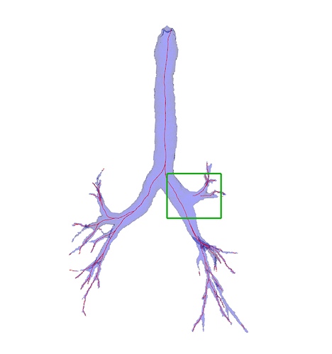
However, I still run into the same problem of same problem of straight “centerlines” traveling outside the model in some cases (I attach a picture below).
I have tried to snap the endpoints to the closest Voronoi Diagram point as you mention in this issue, but it does not seem to change anything. I attach the code I used for the modification of the endpoints:
# Instance Extract Centerline Widget
extractCenterlineWidget = slicer.modules.extractcenterline.widgetRepresentation().self()

# Set up parameter node
parameterNode = slicer.mrmlScene.GetSingletonNode("ExtractCenterline", "vtkMRMLScriptedModuleNode")
extractCenterlineWidget.setParameterNode(parameterNode)

# Set up widget
extractCenterlineWidget.setup()

# Update from GUI to get segmentationNode as inputSurfaceNode
extractCenterlineWidget.updateParameterNodeFromGUI()
# Set network node reference to new empty node
extractCenterlineWidget._parameterNode.SetNodeReferenceID("InputSurface", segmentationNode.GetID())

# Autodetect endpoints
extractCenterlineWidget.onAutoDetectEndPoints()

extractCenterlineWidget.updateGUIFromParameterNode()

# Create new Surface model node for the centerline model
voronoiDiagramNode = slicer.mrmlScene.AddNewNodeByClass("vtkMRMLModelNode")
# Set centerline node reference to new empty node
extractCenterlineWidget._parameterNode.SetNodeReferenceID("VoronoiDiagram", voronoiDiagramNode.GetID())
extractCenterlineWidget.onApplyButton()

endpointsNode = slicer.util.getNode(extractCenterlineWidget._parameterNode.GetNodeReferenceID("EndPoints"))

voronoiDiagramPointsArray = np.ndarray([voronoiDiagramNode.GetPolyData().GetNumberOfPoints() // 10, 3])
for idx in range(voronoiDiagramNode.GetPolyData().GetNumberOfPoints() // 10):
    voronoiDiagramPointsArray[idx] = voronoiDiagramNode.GetPolyData().GetPoints().GetPoint(idx * 10)

endpointsVoronoiNormArray = np.ndarray([endpointsNode.GetNumberOfMarkups(), voronoiDiagramNode.GetPolyData().GetNumberOfPoints() // 10])

for idx in range(endpointsNode.GetNumberOfMarkups()):
    for idx2 in range(voronoiDiagramNode.GetPolyData().GetNumberOfPoints() // 10):
        endpointsVoronoiNormArray[idx][idx2] = np.linalg.norm(endpointsNode.GetCurvePoints().GetPoint(idx) - voronoiDiagramPointsArray[idx2])

endpointsArgVoronoiNormArray = np.argmin(endpointsVoronoiNormArray, axis=1)

for idx in range(endpointsNode.GetNumberOfMarkups()):
    endpointsNode.GetCurvePoints().SetPoint(idx, voronoiDiagramNode.GetPolyData().GetPoints().GetPoint(endpointsArgVoronoiNormArray[idx] * 10))

extractCenterlineWidget.updateGUIFromParameterNode()

# Set network node reference to new empty node
extractCenterlineWidget._parameterNode.SetNodeReferenceID("InputSurface", segmentationNode.GetID())
# extractCenterlineWidget._parameterNode.SetNodeReferenceID("InputSurface", segmentationNode.GetID())
# Create new Surface model node for the centerline model
centerlineModelNode = slicer.mrmlScene.AddNewNodeByClass("vtkMRMLModelNode")
# Set centerline node reference to new empty node
extractCenterlineWidget._parameterNode.SetNodeReferenceID("CenterlineModel", centerlineModelNode.GetID())
extractCenterlineWidget.onApplyButton()
Note that I only check one in every 10 points from the Voronoi diagram to speed up the computation. Do you see why the code would not work? I can provide more context if necessary. This basically assumes that you have a volume which you have segmented (and stored the segmentation in the segmentationNode).
You change the resolution of the image after you loaded it into 3D Slicer. For example, you can use Crop volume module with a spacing scaling of 0.3-0.6. Since Slicer performs all nodes in physical space (images, models, curves, etc.), resampling does not affect quantification results (other than a finer-resolution image can represent small details more accurately).
Thanks, this is useful information. Maybe you need to move the points further inside the Voronoi model.
That is exactly what I do (with the binary map, since my segmentation process is external to 3D Slicer). I use nearest neighbours, isotropic spacing and a scaling of 0.5. The resulting segment has a very rough surface (the cubic voxel shape is everywhere all over the outside), but following what you say I understand that that does not matter for the correct quantification of centerline measurements (e.g. radius). Am I correct here? It would be useful to skip the smoothing process if necessary, I am not completely sure if what you are saying
I tried moving them twice the distance towards the direction of the closest Voronoi diagram point, but that still does not change the resulting centerline sometimes.
I have ended up making a small function to relocate the endpoints to a nearby position further inside the segmentation. It selects a small region (10 * 10 * 10 voxels or so, this could be tuned further) around the endpoint and moves the endpoint to the centroid of the closest segment inside this region (since it is a randomly selected region several segments could be included). So far it has been flawless for me, and I haven’t had to use the Margins tool.
What I meant is to crop&resample the input image, before segmentation.
If you already have a binary labelmap then resampling it with nearest neighbor method will not make the surface any smoother. To interpolate a labelmap so that you get smoother surface, you may need to use an anti-alias filter on the input (such as Gaussian smoothing), interpolate using a higher-order kernel (bilinear, bspline, sinc, …) and threshold the result. You may also try the “Resample image (BRAINS)” module that has a special “binary” mode for labelmap interpolation.
This information is already useful, but it would be even better if you could share the resulting code so that others don’t have to reimplement this if they run into similar issues.
def robustEndPointDetection(endpoint, segmentation, aff, n=5):
    ''' Relocates automatically detected endpoints to the center of mass of the closest component
    inside a local region around the endpoint (defined by n).

    Takes the endpoint position, converts it to voxel coordinates with the affine matrix, then defines a region
    of (2 * n) ^ 3 voxels centered around the endpoint. Then components inside the local region are treated
    as separate objects. The minimum distance from theese objects to the endpoint is computed, and from
    these, the object with the smallest distance to the endpoint is chosen to compute the centroid, which
    is converted back to RAS with the affine matrix.

    Arguments:
        - endpoint <np.array>: position of the endpoint in RAS coordinates.
        - segmentation <np.array>: numpy array corresponding to the croppedVolumeNode.
        - aff <np.array>: affine matrix corresponding ot he nifti file.
        - n <int>: defines size of the region around the endpoint that is analyzed for this method.

    Returns:
        - newEndpoint <np.array>: new position of the endpoint.

    '''

    from skimage.measure import regionprops, label
    from scipy import ndimage

    # Compute RAS coordinates in voxel coordinates with affine matrix
    R0, A0, S0 = np.round(np.matmul(np.linalg.inv(aff), np.append(endpoint, 1.0))[:3]).astype(int)

    # Mask the segmentation (Only region of interest)
    maskedSegmentation = segmentation[np.max([0, S0 - n]): np.min([segmentation.shape[0], S0 + n]),
                                      np.max([0, A0 - n]): np.min([segmentation.shape[1], A0 + n]),
                                      np.max([0, R0 - n]): np.min([segmentation.shape[2], R0 + n])]

    # Divide into different connected components
    labelMask = label(maskedSegmentation)

    labels = np.sort(np.unique(labelMask))
    labels = np.delete(labels, np.where([labels == 0]))

    labelMaskOneHot = np.zeros([len(labels), labelMask.shape[0], labelMask.shape[1], labelMask.shape[2]], dtype=np.uint8)
    for idx, label in enumerate(labels):
        labelMaskOneHot[idx][labelMask == label] = 1

    invertedLabelMaskOneHot = np.ones_like(labelMaskOneHot) - labelMaskOneHot

    # Get distance transform for each and get only closest component
    distanceLabels = np.empty_like(labels, dtype = np.float)
    for idx in range(len(labels)):
        distanceLabels[idx] = ndimage.distance_transform_edt(invertedLabelMaskOneHot[idx])[invertedLabelMaskOneHot.shape[1] // 2][invertedLabelMaskOneHot.shape[2] // 2][invertedLabelMaskOneHot.shape[3] // 2]

    mask = np.zeros_like(segmentation)
    mask[np.max([0, S0 - n]): np.min([segmentation.shape[0], S0 + n]),
         np.max([0, A0 - n]): np.min([segmentation.shape[1], A0 + n]),
         np.max([0, R0 - n]): np.min([segmentation.shape[2], R0 + n])] = labelMaskOneHot[np.argmin(distanceLabels)]

    # Get the centroid of the foregroud region
    properties = regionprops(mask.astype(np.int), mask.astype(np.int))
    centerOfMass = np.array(properties[0].centroid)[[2, 1, 0]]

    # Return the new position of the endpoint as RAS coordinates
    return np.matmul(aff, np.append(centerOfMass, 1.0))[:3]
In my case, I get the affine matrix using the nibabel package, directly from the NIfTI file itself:
aff = nib.load("/path/to/nifti.nii.gz").affine
I initially tried this, but the smoothing filters were either too aggressive on the small vessels (these would vanish) or too soft for larger vessels.
In order to get everything a little more wrapped up, I now extract the segmentation numpy array from the labelmapVolumeNode associated with the segmentation node, and get the affine matrix from the same labelmapVolumeNode:
# Get volume node array from segmentation node
labelmapVolumeNode = slicer.mrmlScene.AddNewNodeByClass('vtkMRMLLabelMapVolumeNode')
slicer.modules.segmentations.logic().ExportAllSegmentsToLabelmapNode(segmentationNode, labelmapVolumeNode)
segmentationArray = slicer.util.arrayFromVolume(labelmapVolumeNode)

# Get affine matrix from segmentation labelMapVolumeNode
vtkAff = vtk.vtkMatrix4x4()
aff = np.eye(4)
labelmapVolumeNode.GetIJKToRASMatrix(vtkAff)
vtkAff.DeepCopy(aff.ravel(), vtkAff)
This solves a couple of small issues you can have in some occasions if you extract the affine matrix from the original NIfTI image, since you can apply some processing to the segmentation itself.