Most Efficient Way of Creating a Thickness Map

Hello,

I have been working on various CMF workflows recently and, in most, our team wants to be capable of generating a thickness map.

My current approach is very simple;

  1. Segment the bony tissue
  2. Hollow the segment
  3. Crop/isolate the region of interest (mostly using scissors)
  4. Separate Outer and Inner surfaces by treating them as islands
  5. Convert Outer and Inner segments into models
  6. Use the Model-to-Model-Distance module to create a distance or thickness map
  7. Visualize distance map using the Shape-Population-Viewer module*
    *Note that I have to account for the thickness of the segments themselves

In a simple bone harvesting workflow, this process works nicely

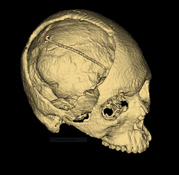
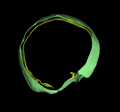
On a cranioplasty workflow, where I am trying to create a thickness map around the bone defect, the process gets a little complicated. Specifically when the edges of the defect reach areas of the ear and nose, where the skull features internal hollow features. In this case;

  1. Segment the bony tissue
  2. Fill internal features/holes/cavities*
  3. Hollow the segment
  4. Crop/isolate the region of interest (mostly using scissors) —> this applies to everything beyond the inner edges of the skull defect
  5. Use a dilated version of the Baffle, created to fix the defect, to crop the inner edges of the bone defect
  6. Separate Outer and Inner surfaces by treating them as islands
  7. Convert Outer and Inner segments into models
  8. Use the Model-to-Model-Distance module to create a distance or thickness map
  9. Visualize distance map using the Shape-Population-Viewer module**

*I would prefer not doing this and rather cut-out the entire area, otherwise I am calculating an inaccurate thickness
**To use the Baffle planner I needed Slicer 4.13 but the Shape-Population-Viewer is not available in this version?

Here are some pictures of the process;

My questions are;
Is there a more elegant way of doing this?
Are there compatibility issues with the Shape-Population-Viewer in 4.13?

PS: I have tried the Thickness-Mapping module with little success, but I am willing to retry if it is the most appropriate method

Thickness-Mapping module should work well if you want to measure thickness along a certain axis.

Otherwise, I would recommend using the workflow described here:

You need to use a segmentation that contains the entire skull bone (not just the thin cortical surfaces but the internal cancellous bone as well).

You don’t need to use Shape Population Viewer to see the color overlay, just go to Models module and click “Visible” checkbox in Display / Scalars section (and select distance as active scalar, if it has not been selected already).

@lassoan,

Thank you for the solution!
Here is a summary of the process, my results, and some follow-up questions.

  1. Generated a label-map from the segmentation of the skull

  2. Created a medial surface from the label-map using the BinaryThinningImageFilter

  3. Created a distance map from the medial surface using the DanielssonDistanceMapImageFilter with Input is Binary = Yes and Use Image Spacing=Yes

  4. Created a thickness/displacement model with the distance map using the Probe Volume with Model

  5. Finally, I can visualize the data using model properties

Remaining questions;

  1. I originally tried making the label-map from the model using the Model to LabelMap extension, but just a right click on the segment seems easier… is this the correct approach?

  2. How do you plot/show/display a color table/bar next to the 3D model?

2 Likes

That’s looking quite nice :+1:

Yes, that is a good way.

There’s a Color Scalar Bar option in the Colors module.

2 Likes

I am working on a similar problem in the heart. In this test case I simply segmented the endocardium and the epicardium and used the model to model distance to create a thickness map. In practice, this may identify areas of scar tissue on the heart. I made an artificial infarct in this test data and the results seem to be good. I am very new to 3D Slicer and am wondering if there is a better way to do this such as described in this thread. I did not have luck reproducing this with my dataset but I think I am happy with the results of the model to model distance. Any suggestions?

Joseph,

Cool application!
Instead of making two models and using model-to-model distance, try replicating the solution to the post.

Keep in mind that the BinaryThinningImageFilter will take a very long time to complete and the loading bar does not seem to be working. I have been using his process for a cranioplasty implant, which should be a pretty simple part to compute, and it took 13 minutes!!!

Here are some suggestions for your model;

  1. Ensure there are no holes between the endocardium and epicardium
  2. Don’t use the entire model, perhaps cut the area of the infarct and some of the surrounding tissue (to start)

As always, let everyone know how it went!

In case anyone is still using medial surfaces for thickness measurement and calculation, I have been working on a consolidated workflow to measure the thickness of cranioplasty implants;

Starting with a model of the implant (or any input surface mesh for that matter), the ThicknessMapping function (below) will complete all of the steps discussed previously, with the addition of some display settings:

For this input model;

The following medial thickness map is generated;


The program generates a blank voxel volume around the model, instead of using the original volume from the reconstruction. This reduces the number of voxels to be processed to calculate the medial surface. For standard 3.0 mm Head CTs I was originally waiting for about 10-13 minutes for the BinaryThinningImageFilter to complete. For this model shown here, the entire program takes about 1-2 mins :grin:

Here is the program, written as a python function. Feel free to use and please give feedback!!!

def ThicknessMapping(self):
        '''
            Thickness Mapping
                Generates and display the thickness of a model throughout its surface.
                The thickness map is calculated using a combination of ITK Filters available to Slicer in python

            References
            [1] How to run a CLI module from Python (https://slicer.readthedocs.io/en/latest/developer_guide/python_faq.html?highlight=CLI#how-to-run-a-cli-module-from-python)
            [2] Running an ITK filter in Python using SimpleITK (https://slicer.readthedocs.io/en/latest/developer_guide/script_repository.html#running-an-itk-filter-in-python-using-simpleitk)
            [3] Create custom color map and display color legend (https://slicer.readthedocs.io/en/latest/developer_guide/script_repository.html#create-custom-color-map-and-display-color-legend)
        '''
        # Flags
        verbose                 = True

        # UI Inputs
        thicknessMapInputModel  = slicer.mrmlScene.GetNodeByID( self._parameterNode.GetNodeReferenceID("ThicknessMapInputModel") )

        # Process
        ## Creating Function Directory 
        shNode                  = slicer.mrmlScene.GetSubjectHierarchyNode()
        folder                  = shNode.CreateFolderItem(shNode.GetSceneItemID(), "Thickness Mapping")

        ## Get Model Centroid and Bounding Box
        inputAssemblyBounds, assemblyBoundingBoxCentroid            = self.logic.getBoundingBoxCentroid( thicknessMapInputModel.GetName(), True )

        ## Generate a Blank,  Bounding Volume
        masterVolumeNodeName                                        = "{}_volume".format( thicknessMapInputModel.GetName() )
        N                                                           = 2.0
        imageSpacing                                                = [1/N,1/N,1/N]
        imageSize                                                   = [int(np.round(inputAssemblyBounds[1]-inputAssemblyBounds[0])*1.10*N),
                                                                        int(np.round(inputAssemblyBounds[3]-inputAssemblyBounds[2])*1.10*N), 
                                                                        int(np.round(inputAssemblyBounds[5]-inputAssemblyBounds[4])*1.10*N)]
        voxelType                                                   = vtk.VTK_UNSIGNED_CHAR
        imageOrigin                                                 = [(assemblyBoundingBoxCentroid[0]-imageSize[0]/(2*N)), 
                                                                    (assemblyBoundingBoxCentroid[1]-imageSize[1]/(2*N)), 
                                                                    (assemblyBoundingBoxCentroid[2]-imageSize[2]/(2*N))]
        
        imageDirections                                             = [[1,0,0], [0,1,0], [0,0,1]]
        fillVoxelValue                                              = 0
        imageData                                                   = vtk.vtkImageData()
        imageData.SetDimensions(imageSize)
        imageData.AllocateScalars(voxelType, 1)
        imageData.GetPointData().GetScalars().Fill(fillVoxelValue)
        masterVolumeNode                                            = slicer.mrmlScene.AddNewNodeByClass("vtkMRMLScalarVolumeNode", masterVolumeNodeName)
        masterVolumeNode.SetOrigin(imageOrigin)
        masterVolumeNode.SetSpacing(imageSpacing)
        masterVolumeNode.SetIJKToRASDirections(imageDirections)
        masterVolumeNode.SetAndObserveImageData(imageData)
        masterVolumeNode.CreateDefaultDisplayNodes()
        masterVolumeNode.CreateDefaultStorageNode()

        shNode.SetItemParent( shNode.GetItemByDataNode(masterVolumeNode), folder )

        # Status
        if (verbose):
            print( "Generated Blank, Bounding Volume..." )

        ## Generate a LabelMap using the Input Model and the Blank Bounding Volume
        modelLabelMapParams                                         = {}
        modelLabelMapParams["InputVolume"]                          = masterVolumeNode
        modelLabelMapParams["surface"]                              = thicknessMapInputModel
        modelLabelMapNode                                           = slicer.mrmlScene.AddNewNodeByClass("vtkMRMLLabelMapVolumeNode","{}_labelmap".format( thicknessMapInputModel.GetName() ))
        modelLabelMapParams["OutputVolume"]                         = modelLabelMapNode
        modelToLabelMap                                             = slicer.modules.modeltolabelmap

        cliNode = slicer.cli.runSync(modelToLabelMap, None, modelLabelMapParams)

        if cliNode.GetStatus() & cliNode.ErrorsMask:
            errorText = cliNode.GetErrorText()
            slicer.mrmlScene.RemoveNode(cliNode)
            raise ValueError("CLI execution failed: " + errorText)
        slicer.mrmlScene.RemoveNode(cliNode)

        shNode.SetItemParent( shNode.GetItemByDataNode(modelLabelMapNode), folder )
        shNode.SetItemParent( shNode.GetItemByDataNode(cliNode), folder )

        # Status
        if (verbose):
            print( "Generated LabelMap from Model..." )

        ## Generating Medial Surface
        inputImage                                                  = sitkUtils.PullVolumeFromSlicer( modelLabelMapNode )
        filter                                                      = sitk.BinaryThinningImageFilter()
        outputImage                                                 = filter.Execute( inputImage )
        medialSurfaceVolumeNode                                     = slicer.mrmlScene.AddNewNodeByClass("vtkMRMLScalarVolumeNode", "{}_medial_surface".format( thicknessMapInputModel.GetName() ))
        sitkUtils.PushVolumeToSlicer(outputImage, medialSurfaceVolumeNode)

        shNode.SetItemParent( shNode.GetItemByDataNode(medialSurfaceVolumeNode), folder )

        # Status
        if (verbose):
            print( "Generated Medial Surface from LabelMap..." )
        
        ## Generating Distance Map
        inputImage                                                  = sitkUtils.PullVolumeFromSlicer( medialSurfaceVolumeNode )
        filter                                                      = sitk.DanielssonDistanceMapImageFilter()
        filter.UseImageSpacingOn()
        filter.InputIsBinaryOn()
        outputImage                                                 = filter.Execute( inputImage )
        distanceMapVolumeNode                                       = slicer.mrmlScene.AddNewNodeByClass("vtkMRMLScalarVolumeNode", "{}_distance_map".format( thicknessMapInputModel.GetName() ))
        sitkUtils.PushVolumeToSlicer(outputImage, distanceMapVolumeNode)

        shNode.SetItemParent( shNode.GetItemByDataNode(distanceMapVolumeNode), folder )

        # Status
        if (verbose):
            print( "Generated Distance Map from Medial Surface..." )

        ## Probe Volume with Model
        probeVolumeWithModelParams                                  = {}
        probeVolumeWithModelParams["InputVolume"]                   = distanceMapVolumeNode
        probeVolumeWithModelParams["InputModel"]                    = thicknessMapInputModel
        thicknessMapNode                                            = slicer.mrmlScene.AddNewNodeByClass("vtkMRMLModelNode","{}_thickness_map".format( thicknessMapInputModel.GetName() ))
        probeVolumeWithModelParams["OutputModel"]                   = thicknessMapNode
        probeVolumeWithModel                                        = slicer.modules.probevolumewithmodel

        cliNode = slicer.cli.runSync(probeVolumeWithModel, None, probeVolumeWithModelParams)

        if cliNode.GetStatus() & cliNode.ErrorsMask:
            errorText = cliNode.GetErrorText()
            slicer.mrmlScene.RemoveNode(cliNode)
            raise ValueError("CLI execution failed: " + errorText)
        slicer.mrmlScene.RemoveNode(cliNode)

        thicknessMapInputModel.GetDisplayNode().SetVisibility(False)

        shNode.SetItemParent( shNode.GetItemByDataNode(thicknessMapNode), folder )
        shNode.SetItemParent( shNode.GetItemByDataNode(cliNode), folder )

        # Status
        if (verbose):
            print( "Generated Thickness Map from Distance Map and Input Model..." )
        
        ## Updating Display Settings, Colormap Labeling
        # First, we set the medial surface volume on the background
        slicer.util.setSliceViewerLayers( background = medialSurfaceVolumeNode, foreground = None, label = None )
        # Here we ensure the thickness model is shwon intersecting all planes
        thicknessMapNode.GetDisplayNode().SetSliceIntersectionVisibility(True)
        thicknessMapNode.GetDisplayNode().SetSliceIntersectionThickness(3)
        # And finally we plot the colormap;
        # To generate the colormap, we need to extract the scalar range associated with the model
        scalars                                                     = vtk_to_numpy( thicknessMapNode.GetPolyData().GetPointData().GetScalars() )
        maxThickness                                                = np.max( scalars )
        minThickness                                                = np.min( scalars )
        avgThickness                                                = np.mean( scalars )

        colorTableTitle                                             = "Medial Thickness (mm)"
        labelFormat                                                 = "%4.1f mm"
        colorTableRange                                             = maxThickness
        # Create color node
        colorNode = slicer.mrmlScene.CreateNodeByClass("vtkMRMLProceduralColorNode")
        colorNode.UnRegister(None)  # to prevent memory leaks
        colorNode.SetName(slicer.mrmlScene.GenerateUniqueName("MedialThicknessMap"))
        colorNode.SetAttribute("Category", "MedialThicknessModule")
        # The color node is a procedural color node, which is saved using a storage node.
        # Hidden nodes are not saved if they use a storage node, therefore
        # the color node must be visible.
        colorNode.SetHideFromEditors(False)
        slicer.mrmlScene.AddNode(colorNode)
        # Specify colormap
        colorMap = colorNode.GetColorTransferFunction()
        colorMap.RemoveAllPoints()
        colorMap.AddRGBPoint(0.0, 0.66, 0.0, 1.0)
        colorMap.AddRGBPoint(0.5, 1.0, 0.0, 1.0)
        colorMap.AddRGBPoint(1.0, 1.0, 0.33, 1.0)
        colorMap.AddRGBPoint(1.5, 1.0, 1.0, 1.0)
        colorMap.AddRGBPoint(2.0, 0.33, 1.0, 1.0)
        colorMap.AddRGBPoint(2.0, 0.0, 1.0, 1.0)
        colorMap.AddRGBPoint(maxThickness, 0.0, 0.66, 1.0)
        # Display color legend
        thicknessMapNode.GetDisplayNode().SetAndObserveColorNodeID(colorNode.GetID())
        colorLegendDisplayNode = slicer.modules.colors.logic().AddDefaultColorLegendDisplayNode(thicknessMapNode)
        colorLegendDisplayNode.SetTitleText(colorTableTitle)
        colorLegendDisplayNode.SetLabelFormat(labelFormat)
        

        # Status
        if (verbose):
            print( "Thickness Mapping Completed...!" )

Hi!
I just started working on this problem - how to get thickness map from cardiac CT in order to visualize scar. Did you manage to find a reproducible workflow?
Thanks!

1 Like

Hi. I am trying to use this function (Slicer 5.6.2) but I get the error
“AttributeError: ‘MRMLCorePython.vtkMRMLModelNode’ object has no attribute ‘_parameterNode’.”
I used this example code
def createModelFromVolume(inputVolumeNode):
“”“Create surface mesh from volume node using CLI module”“”

parameters = {}
parameters[“InputVolume”] = inputVolumeNode
outputModelNode = slicer.mrmlScene.AddNewNodeByClass(“vtkMRMLModelNode”)
parameters[“OutputGeometry”] = outputModelNode

grayMaker = slicer.modules.grayscalemodelmaker
cliNode = slicer.cli.runSync(grayMaker, None, parameters)

if cliNode.GetStatus() & cliNode.ErrorsMask:

errorText = cliNode.GetErrorText()
slicer.mrmlScene.RemoveNode(cliNode)
raise ValueError("CLI execution failed: " + errorText)

slicer.mrmlScene.RemoveNode(cliNode)
return outputModelNode
from Python FAQ — 3D Slicer documentation to create the model.
Anyone can help me understand how to go forward?

Thanks, Daniele.