Dears 3DSlicer developers:
Andras Lasso, Csaba Pinter, Andrey Fedorov, Steve Pieper and Thomas Vaughan
Firstly, I Should thank you for all tips and guidances in 3DSlicer and python programming.
In the beginning, I will explain our project and then the steps done briefly.
We defined the project to correct geometric distortion in MRI imaging based on CT imaging. As you definitely know, this problem is occurred in MRI imaging due to the non-uniformity of static and gradient magnetic fields.
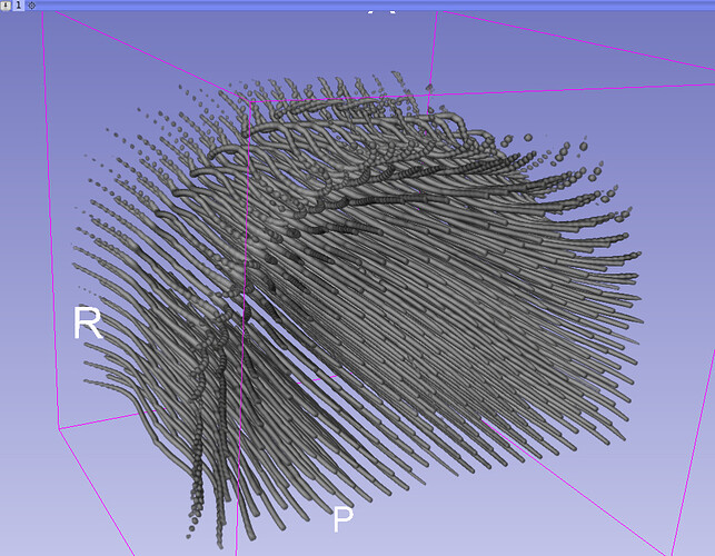
To correct this distortion, a phantom was designed and fabricated. This phantom consists of 305 plastic pipes containing water and five perspex sheets drilled to fix these pipes. Except for one of the pipes that was inserted obliquely, the other pipes were aligned in parallel.
The following figures represent 3D views of it.
In CT imaging:
In MRI imaging:
Since the geometric distortion is not uniform in the entire FOV of MR, It turns out that the best transformation matrix is found by B-Spline transform to correct this type of distortion. I think that this B-spline transform should be calculated in the entire FOV of MRI. The geometric distortion in MRI imaging can be corrected by using this transform matrix.
Overview of the steps in calculating B-Spline matrix:
-
Equalize “Image Dimensions”, “Image Spacing” and “Image Origin” between CT and MRI images
-
Segment the phantom pipes in two CT and MR imaging
-
Extract the centerlines of the phantom pipes in two CT and MR imaging using vmtk.
The following figure shows the centerlines of CT and MR images along with axial plane, respectively.
Centerlines CT:
Centerlines MR:
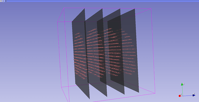
- Calculate the collision points between CT and MR centerlines with axial plans apart at intervals 100 mm.
Schematic design the centerlines CT and four axial plans
Schematic design the centerlines MR and four axial plans
Schematic design the collision points centerlines CT and four axial plans
Schematic design the collision points centerlines MR and four axial plans
-
Convert these collision points to markups with the names C and M for CT and MR centerlines.
The number of corresponding markups is equal to 1101 in CT and MR. -
Calculate the B-Spline transform matrix based on the alignment of C and M Markups using “Scattered Transform” module.
The following figure shows screenshot the module of “Scattered Transform”.
As you see, I set “Initial landmarks” to C (CT markups) and “Displaced landmarks” to M (MR markups). Is it true with considering CT as Fixed Image and MR as Moving Image?
I have some questions as following:
-
Do you think I’ve done the right steps?
-
To increase the accuracy in the calculation of B-Spline transform, should I increase “B-Spline Grid Spacing” in the section of “Advanced parameters” in the module of “Scattered Transform”?
-
How can I apply this B-Spline Transform to MR images for registration CT and MR?
Please guide me,
Thanks a lot.
Shahrokh


