It’s been a week that I am struggling with the new dataset that I received including ultrasound/MRI and their corresponding STL files. As I have mentioned earlier, I wrote the code and successfully combined STLs an exported to NRRD based on their corresponding MRI images. On the other hand, our STL files have been made for both Ultrasound and MRI.
However, similar to this issue, when I load US volumes and corresponding STLs, the STL files are totally off. I followed your recommendation to convert LPS/RPS for coordinate mismatch, but that didn’t help. Even, I tried to set the origin, pixel spacing and view direction of exported nrrd as US volume, but still the segmentation output is totally outside of the region.
The STL files have been generated couple of years ago with 3D slicer. I thought maybe that is the issue.
You can try other transforms, adjust 180 degrees, the stl will be aligned with the volume. I’m not sure which mode is more suitable, but this kind of coordinate change is not 1 degree and 2 degrees, but 180 degrees, so it is easier to adjust
If these are old models, than the coordinate system is probably RAS. Drag and drop them into Slicer, in Load data dialog box, expand options and change the Coordinate System from default to RAS.
One question, do the models also store their origin/pixel-spacing information like normal volume?
When I export the STL file to nrrd segmentation output, I tried to set the origin and spacing the same as actual volume, with the hope that this enforces the alignment. However, the segmentation is still off the actual view.
Input nodes
volumeNode   = slicer.util.loadVolume(usPath)
prostateNode = slicer.util.loadSegmentation(prosSegPath)

if usPath is not None:
    usNode = slicer.util.loadVolume(usPath)
    spacing = usNode.GetSpacing()
    origin = usNode.GetOrigin()

# Write segmentation to labelmap volume node with a geometry that matches the volume node
labelmapVolumeNode1 = slicer.mrmlScene.AddNewNodeByClass('vtkMRMLLabelMapVolumeNode')
slicer.modules.segmentations.logic().ExportVisibleSegmentsToLabelmapNode(prostateNode, labelmapVolumeNode1, volumeNode)

labelmapVolumeNode1.SetOrigin(origin)
labelmapVolumeNode1.SetSpacing(spacing)
Do you have the MRML scene? There may be transforms in the scene that you need to apply.
If you know which version was used to save this scene then please check if that version loads it correctly. (all previous releases are available on the Slicer download page)
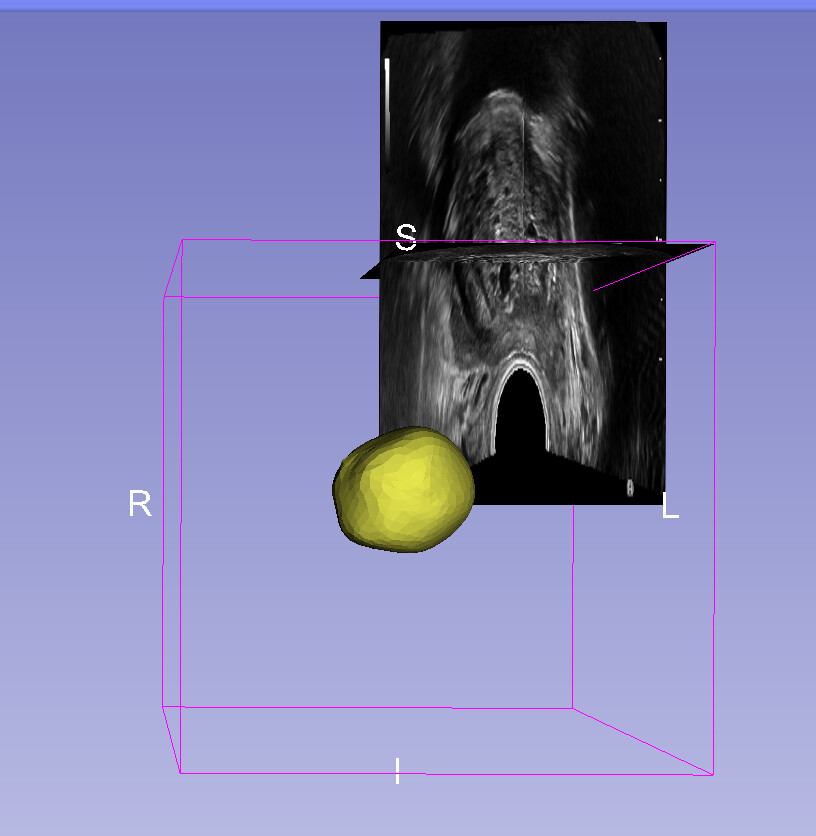
Unfortunately I don’t have MRML scene files. I did some more investigations. If I load first the stl file, it will be in the center of the view window, and then I load the volume (US image). It will be out of the scene but If I press the “Center Volume” button from Volumes tab, both STL model and volume are align together. Even though the direction of STL is not fully match, but I can set that. Now, If I do the reverse and first load the volume and then STL file, I can not have this alignment neither in Python code nor in Slicer window.
Any idea, how to set the US volume always to the center?