Hello!
I have a question.
I want to implement volume rendering using vtk.js and overlay the segmented stl.
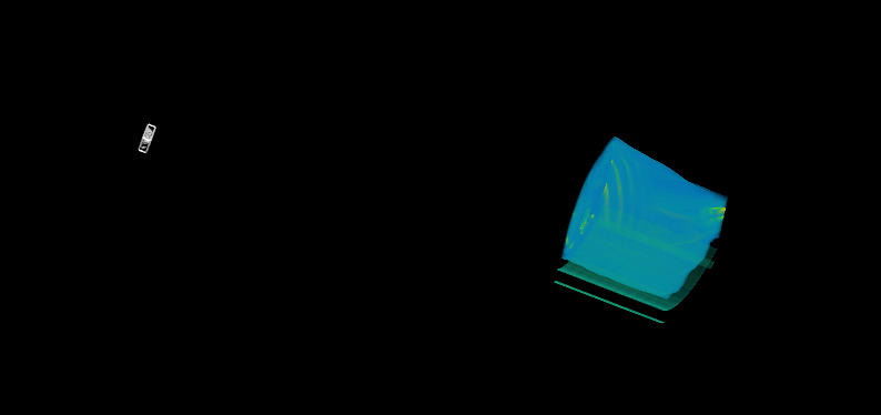
The following figure shows a screen with volume rendering and stl at the same time.
The problem occured here.
I used a 3d slicer to export stl and apply it, but it is not overlayed exactly.
I assumed that the location value would be the same because it was an exported stl file from the same dicom file.
But the result seems to be not.
Is there an option to equalize positions in 3d slicer? Or is there a part I misunderstood in use?
+(In the same dicom, vti files are exported from paraview and stl files are exported with 3dslicer)
lassoan
May 17, 2019, 3:11am
2
What coordinate system vtk.js renderer is using? LPS or RAS? Slicer uses RAS but LPS is more common. You may need to flip the first two axes (or choose LPS coordinate system when you export the segmentation using “Export to files”).
Thank you for your comment.
The coordinate system of vtk.js seems to be LPS.
I am currently following your advice.
The STL was exported based on the LPS system. The exported stl seems binary, is there an option to choose ascii?
Because my code does not seem to read the binary right now. So I have to select the ascii through the blender and save the stl file to render it.
As a result, the same result was obtained. Is it a problem to re-export stl files in ascii format via blender?
Thank you!!
lassoan
May 17, 2019, 11:44am
5
Text format STL is very is much slower to read and takes much more space, so I would not complicate the segmentation export with an ASCII option.
However, you can read the binary STL file and write it as ASCII STL with a few lines of Python code (vtkSTLReader , vtkSTLWriter ).
Thank you for your comment
I also think Text format STL is very inefficient.
I am using vtk.js. I’ll take a closer look at the STLReader in vtk.js.
Thanks!