I have never worked with 3D Slicer before and I am quiet new in this field. But I would like create a 3D model out of CT-DICOM-data. It is important that the HU values of the cortical and trabecular bone will be safed in the output (as .igs) for further Finite element analysis in ABAQUS or FEBio.
Furthermore I would like to know if it is possible in 3D Slicer to do material assignment and volumetric meshing.
I would appreciate any support.
Thank you in advance
You can segment spine CT in Slicer and use Segment Mesher module (provided by SegmentMesher extension) to create a FE mesh. Segment Mesher uses Cleaver2 for mesh generation, which is developed by the same group as FEBio, so it should be compatible with it.
Thanks a lot for your fast reply Mr. Lasso, I really appreciate it. So did I understood it correctly that with the extension I can create tetrahedral (volumetric) meshes? Ho about the assignment of material properties?
I also read that I need another software like Autodesk Meshmixer to smoothen the 3D object prior FE analysis, is that correct?
Yes.
The segment index is saved as cell scalar in the mesh. In your mesh preprocessor, you should be able to select part of the mesh based on this cell scalar and define material properties.
Cleaver (the mesher that Segment Mesher module uses by default) creates smooth meshes. You can adjust meshing parameters to control resolution and smoothness. You should not need any other postprocessing. Meshmixer wouldn’t work anyway, as it can only deal with surface meshes.
Dear Mr. Lasso,
finally I have created a model of an lumbar vertebra out of DICOM data. I premeshed it as you suggested via Segment Mesher Modul and eported the the model as .stl and .obj file. The problem I am facing now is that I cannot load a volume mesh into FeBio (only .stl files). Do you know how or what I should do?
Thanks a lot for your advices in advance
FeBio Studio can import CTK unstructured grid saved in legacy VTK file format in ASCII mode. You can generate such file in Slicer by choosing “Unstructured grid (.vtk)” as File Format and uncheck “Compress” option (click “Show options” checkbox if you don’t see the options). Unfortunately, FeBio Studio is still in beta and has many issues. If you find that it has trouble opening your file then report it (see feedback email address here).
Thanks a lot for your help!
I tried to safe the file as .vtk but still cannot load it into FEBio. I can only load the .stl file as binary format. Hence I wrote FEBio, if there is any other possibilitie. I will keep you updated.
Do you know if ABAQUS is better in this case?
I’ve just talked to the developer of FEBio Studio about this and he fixed unstructured grid import from ASCII VTK files today. I don’t know when he will update the FEBio download page, so ask him on the FEBio forum or at the contact email address.
Thank you so much for your efforts!
I tried to safe another 3D model in .vtk but it is showing me this error: "Cannot write data file: C:/Users/Admin/Documents/Jeffs-Data/Test/5. Trial_ Threshold_300-1800 L5/23052020_L5/LabelMapVolume.vtk.
Do you want to continue saving?
Do you know what is the problem?
Likely a permission issue. Try to save to a folder where you have right permission.
Also make sure you don’t have any special characters in any of the folder or file names.
You might find some more details in the application log.


How to biomechanical analysis of the vertebra:
- solidify the bone using “Wrap solidify” effect (provided by SurfaceWrapSolidify extension)
- generate a volumetric mesh using SegmentMesher extension
- save generated volumetric mesh with “Compress” option disabled into .vtk file
- load .vtk file into FeBIO Studio
Dear Mr. Lasso thank you for your reply!
Unfortunately today the extension database did not work, so I could not try the SurfaceWrapSolidify extension yet
But I am also not sure if this solidifying module can lead to the model I need, cause I think for a precise FE analysis I need to model the cancellous bone as well and with this module it seems, that the cancellous bone will be extracted? Please correct me if I am wrong
Unfortunately today the extension database did not work
Every day the Slicer Preview Release shows up around 1am EST but extension builds are completed around 10am EST, so depending on your timezone, you may not see extensions for a while. You can retry installing extensions now or install yesterday’s release (Download 3D Slicer | 3D Slicer).
The holes you see in the mesh are not there because you have such big holes in the bone. It is a segmentation error, because the average intensity of the bone decreases due to partial volume effect and it becomes so similar to soft tissue’s intensity that they become classified as soft tissue = outside segmentation.
Therefore, you need to fill in these “holes” in the segment and to reproduce material properties, you set different material properties within this mesh. You can take samples of the CT volume at every mesh point to decide where in the mesh you set material properties corresponding to cortical/cancellous bone.

The main issue is that you have chosen to enable “Create shell” and chose thickness that is comparable to your voxel size.
If the goal is finite-element analysis then a shell is not a good model, so do not enable “Create shell” option.
You will get material IDs (corresponding to segment indices) when Segment mesher module creates a volumetric mesh using Cleaver2. You can also add CT density values to the volumetric mesh using Probe volume with model module.
Your FEM software can use these additional scalar values in your mesh to set material properties. I don’t know which FEM package can read VTK unstructured grids and which can use material IDs or density values stored in cell scalars, but you can ask their developers and report back to us what you learned.
Thank you very much for your help. I finally created a volumetric model of the vertebra with the following adjustmens:
- Wrap solidify module → Carve holes: 1mm
- Smoothing → Closing(fill holes): 1mm
- Gaussian Filter: 1mm
The result looks like that:

but the problem now is, if I want to mesh it, I get a very edged and reduced model. I tried different paramaters and this seems the best (but still not good enough): scale= 3; multiplier=1; grading=5
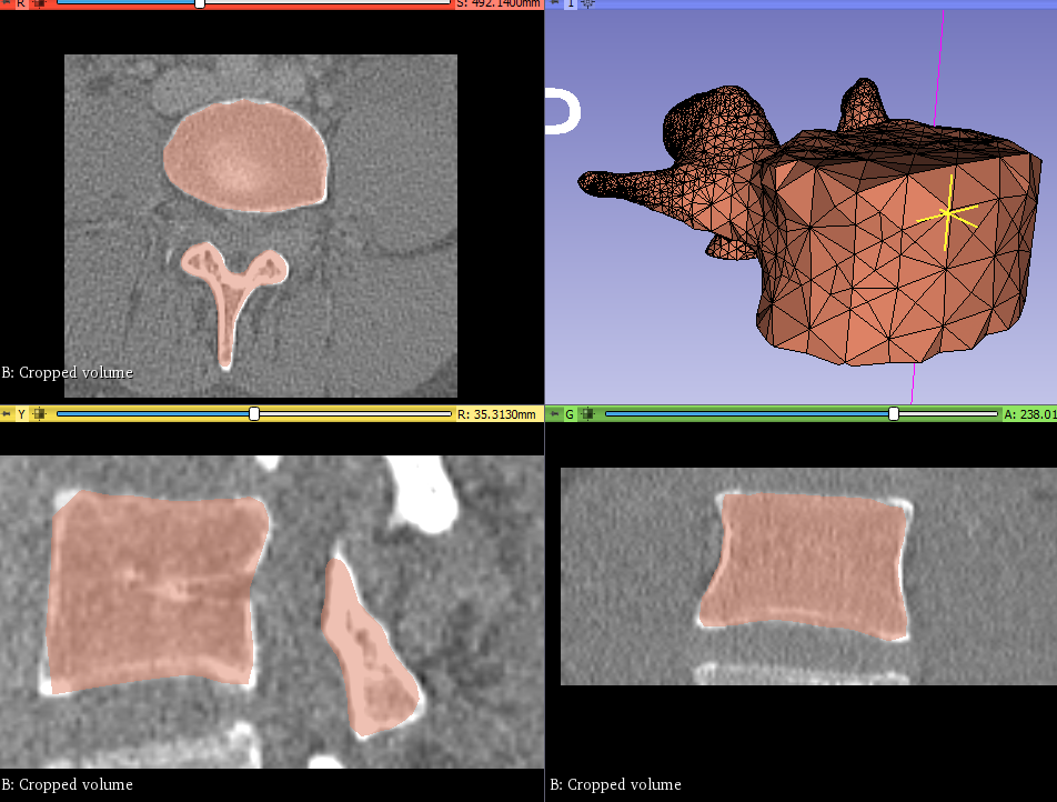
Any idea, what I am doing wrong or what I should improve?
This looks really nice. Your volumetric mesh resolution looks very good, too, but of course you may want to adjust the mesh depending on what you want to model (heat transfer, mechanical stresses, etc.) and where.
Note that computational mesh does not have to be as high resolution as the visualization mesh. It would result in unnecessarily complex mesh, leading to very long computation times and robustness issues. Computational mesh surface does not have to be smooth either, except in special cases (such as when you are specifically interested in modeling surface contacts). Once the computation is complete, you can transfer displacements or other computed values over the visualization mesh.
What kind of modeling do you plan to do?