I suspect this is due to each segment being smoothed independently in the conversion to the closed surface representation. In the Segmentations module, click the dropdown next to “Closed Surface” to access and modify the conversion parameters.
This will raise the following window:
Click on the conversion path step (the line in the upper section), and then try changing the Joint smoothing flag to 1.
I tried a quick search in the documentation to see if I could find a reference to this, but didn’t find anything. However, I think this should do what you want.
Your source representation (i.e. the one that you can consider most faithful to the real world object) is binary labelmap. When you convert these labelmaps to closed surface, then by default you apply smoothing. If the artifacts you get from smoothing are undesired, then you can always disable smoothing.
In that case, however, you get a surface that consists of blocks and it cannot be rendered nicely. Another thing you can do is supersample the segmentation’s binary labelmap, so that it has a higher resolution than the anatomical image. Then you may do less smoothing when you do the conversion to reduce the artifacts you do not want.
Thanks for the detailed references @cpinter! Since it looks like you are the expert on this, can you describe what the “Joint smoothing” parameter does in the conversion, if it is not ensuring that touching surfaces do not overlap?
@mau_igna_06 it would be good if you could try the JointSmoothing option from the older ModelMaker. That mode was specifically added to provide watertight boundaries because the vertices of both models were moved identically during the smoothing process, so there was never any gap between the meshes for adjacent segments. There may still be some aspects of the older code that need to be incorporated in the segmentations infrastructure.
This topic has come up before, but it’s still not clear to me that we can easily get the same output meshes that we get with ModelMaker.
By enabling “Joint smoothing” option in segmentation conversion parameters, we perform the exact same algorithm as in the Model maker module. The only difference is that it is performed for each layer. If your segments are non-overlapping but they are in separate layers (e.g., because you enabled overlap before) then you can collapse them into one layer in Segmentations module’s Layers section.
If the segments were overlapping then yes, I can see they cannot be made watertight. But I still don’t see that this is the case in the data @mau_igna_06 posted. It will be good to get some clarity on on this.
I just tried joint smoothing (5.5.0-2023-11-10 r32231 / 48b6d55, Win11), and I found that if smoothing factor is larger than 0, then we lose the triangles.
Btw I never used joint smoothing here in the conversion parameters but I assume that it should work preserving the cells.
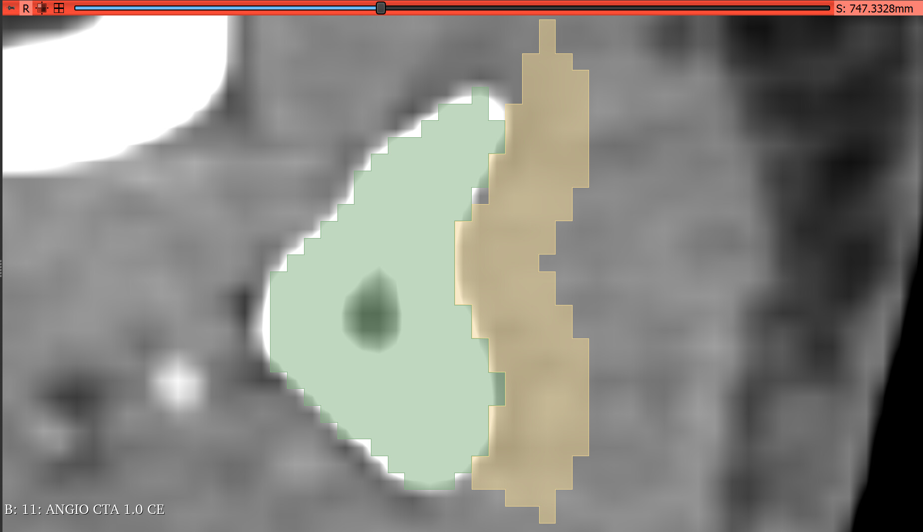
I tried all last three options on the dialog, to update the 3D surface of two touching segments on a segmentation, then exported them as models and named the different resulting folders as a binary table (e.g. folder named 100 means it was created using conversion parameters “Joint smoothing”=1, “SurfaceNets smoothing”=0, “Conversion method”=0)
I’m not sure I fully follow all the results here. Is your conclusion that you were only able to achieve non-collision by accepting bad smoothing? That is, there was not a method you found which gave good smoothing results without also introducing overlaps or inappropriate gaps between smoothed segments?
I’m surprised. From my admittedly naïve perspective, I don’t see why this is an especially difficult problem. It is easily detectable from the source labelmap exactly where two segments are in contact. Couldn’t that contact surface be smoothed, and then that shared surface be connected to each of the two segments for that region of the smoothed representation (with same triangluation but reversed surface normals for each to keep the proper sense of inside vs outside)? Mentally, that’s what I always assumed “joint smoothing” was doing under the hood.
This is exactly what I had understood too based on the description from Bill Lorensen back in the day that he was using this algorithm and then doing the same mesh operations to both sides of the shared interface. But I checked with Mauro’s data by exporting to labelmap and running JointSmoothing in ModelMaker and it does have the same behavior. Looking at the implementation it seems that it doesn’t use the Cuberille approach.