Joint smoothing can create spurious bridges between separate parts of anatomy (in same segment)

In the Segment Editor module there are various options for Smoothing in the Effects panel.
One favourable choice is Joint smoothing, which brings up the note: “smoothes multiple segments at once, preserving watertight interface between them”.

I had in mind (from a little experience) that Joint smoothing would not tend to create (spurious) ‘bridges’ between different parts of an individual segment, nor would it delete (real) ‘bridges’.
For instance, if the unsmoothed segment looked like the letter “H” (or the symbol “”), it wouldn’t delete the (possibly narrow) crossbar, but if the unsmoothed segment looked like “II” (double uppercase “i”), it wouldn’t merge these, and if the unsmoothed segment looked like Greek letter “Ω”, it wouldn’t create any crossbar to bridge across the base.
Certainly the other built-in smoothing options seem more prone to create those artefacts in the case of small gaps or thin segments.

However, I may have oversimplified what the algorithm does. (Or there may be some small implementational quirks, per Exported STL files from the segmentation has intersection/penetration - #11 by lassoan ?)

I found that actually it may create spurious bridges.
In the screenshots below the green is the original segment (with a narrow gap created with the Scissors effect), and the brown is after applying the Joint smoothing effect, with Smoothing factor equal to 0.5.


Other than this the smoothing looks good.

If this is expected behaviour, is there a recommendation to avoid it? For example, would applying joint smoothing five times with Smoothing factor equal to 0.1 be theoretically equivalent? (I guess it wouldn’t.)

Did you try creating a segment that selects all the volume except your region of interest with boolean fill and boolean difference?

Then with your original segment and the newly created segment visible execute joint smoothing and the bridges should not appear.

That could work I think. I’m not sure.

We’ve been discussing this for quite a while and I’m still thinking there’s a difference between the Joint Smoothing exposed by the current Segmentations and the Joint Smoothing originally provided by @Lorensen. As dicussed, @Lorensen’s algorithm maintained watertight boundaries by explicitly moving the corresponding vertices where to models abut such that they have the exact same location in the algorithm output (e.g. two STL files would have exact watertight fit). Last I checked, as in the screenshots linked above, the current implementation can still leave some (small) gaps.

Also @Lorensen’s algorithm should never change the topology, since it works by first building surfaces that exactly follow the voxel edges (a ‘cuberile’ model) and then only smooths by moving the vertex points.

The “bridges” in the image above are probably simply due to converting the smoothed result back to a binary labelmap. If you have the same voxel value in two adjacent voxels in a labelmap (without a gap or different segment between them) then the two voxels are considered connected (fused).

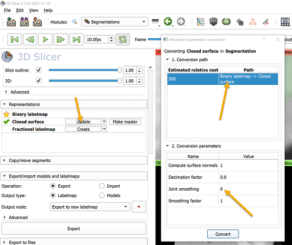
You have several options to address this. The most obvious one is to only smooth the mesh, not the labelmap. You can control mesh smoothness using “Smoothing factor” in the dropdown menu of “Show 3D” button. If you want to smooth the labelmap then you may need to increase the resolution of the segmentation so that you can reliably represent a very narrow gap.

This method is only applicable when segments do not overlap and all the labels are in a single volume.

Until a few years ago, segmentations module stored each segment in a separate labelmap, therefore the method was not feasible (due to potentially overlapping segments); and if segments did not overlap, merging the segments after each segment update would have been just too slow.

After @Sunderlandkyl implemented shared labelmap support in Segmentations, he added the “Joint smoothing” option to the closed surface generation method. Since then you can use the exact same method as the original “Model maker” module used for smoothing the output models. If the option is enabled, then segments in the same layer are smoothed jointly.

If the labelmap is isotropic and smoothing is only used for removing staircase artifacts (and not to smooth out some valid details of the mesh) then joint smoothing should not make a difference, though.

Yes, and this is a very common use case - in fact, required if watertightness is the goal.

How about making this true by default but changing the definition to “Joint smoothing unless segments overlap”.

First of all it’s good to be able to build a more detailed understanding of the difference between the smoothing under the Show 3D button and the joint smoothing algorithm applied under the Smoothing effect. I suppose that implicitly I had an idea that the former smooths the surface representing the boundary of the segmented voxels (which you call the mesh), while the latter smooths the segment by adding or removing voxels (which you call the labelmap). Thank-you for additional clarification.

For the record (as some of you would already have realised), the above screenshots were taken without any mesh smoothing. I presented the geometry in this way so that the source of the artefacts would be more immediately obvious.

If I apply mesh smoothing to the above two segments, with Smoothing factor equal to 0.5, then the results are as below.


So indeed the gap is preserved by smoothing the mesh, rather than the labelmap.
However, aside from the bridging artefacts, I prefer the smoothing obtained by smoothing the labelmap first and then smoothing the mesh.

While this is a logical suggestion, there may be a couple of potential issues.

Firstly, I have already increased the resolution by a minimum of fourfold in each orthogonal direction by isotropic cropping in the Crop Volume module.
I’m reluctant to increase the resolution of the cropped volume much more than that, because it may create massive 3D rasters that would be (I think) slower to process. Especially so if I go through slice-by-slice to manually amend the initial results (obtained by thresholding or grow-from-seeds, say).

I’m also not sure that it’d be suitable to increase the resolution of the labelmap only.
Presumably this would be done through the Segmentation geometry dialogue, per the screenshot below. [DIGRESSION: we’ve had a little discussion of this topic before. Incidentally, it seems a little inconsistent that in this dialogue a factor >1 is needed to increase resolution, whereas in the Crop Volume module a factor <1 is needed to increase resolution.]


The additional issue I anticipate is that then the smoothing would end up being highly localised (or ‘small scale’). Suppose I have two 5-millimetre objects separated by a small gap (say 0.2 mm). If I use a resolution of, say, 0.05 mm, then most likely the gap will be preserved, but I may end up with smooth medium-sized artefacts (0.5–1 mm bumps, say) on the larger objects that I’m unable to smooth away. Or, to put it another way, I imagine that the smoothing kernel (or some equivalent) will be smaller if the resolution is increased.

In the end I think the results look best if I manually erase the erroneous voxels, as below.

—DIV

That is, I think, what I have: all of the voxels of interest are in a single segment — and it is the only segment being smoothed.

I expect that the bridges would definitely not appear if I cut the existing segment into two parts (one on each side of the narrow gap). But that could create a different problem later when I would have to try to rejoin them (because the final objective is a single segment).

Thank-you for the suggestion, Mauro.
I made a tiny adjustment to your method, which was to create the complementary segment using the logical operations of Copy and Invert.

I then tried the joint smoothing (of the labelmap) again in two different situations: (i) with the inverted segment listed first in the segments table, with the result shown in purple below; and (ii) with the inverted segment listed last in the segments table, with the result shown in reddish-brown below. As you can see, the spurious bridges are still created.
The order of segments in the segments table made no difference at all. The results are very slightly different to the original results I obtained.