Tracking of multiple objects to a reference

Hi all,

I’ve been working with slicerIGT to create a surgical navigation tool for the ankle.
In this tool, we want to track the position of the Fibula (calf bone) with respect to the reference Tibia (shin bone).

To try this, we have 3D printed STL models of the fibula and tibia, which we got from a CT scan.

We are yet able to track the tibia (which we have used as reference, similar to the neurosurgery tutorial) and the stylus. I’m having some difficulties however with tracking the fibula with respect to the tibia.

How should I perform the transformation matrix to align the fibula STL model also with respect to the reference tibia?

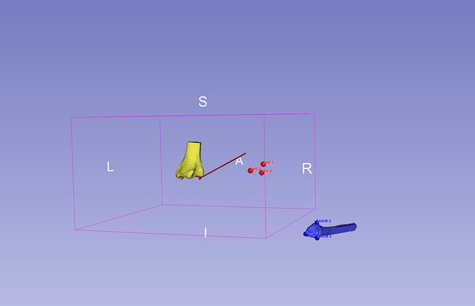
See below A picture of the setup, slicer view and current transforms, which shows a good tracking capability of the tibia and stylus, but the fibula is out of place.

image

Thank you!

“Reference” is the markers that are attached to the tibia?

If you want the tibia to remain static, while the fibula moves, I would add it to the transform hierarchy like so:

- ReferenceToRAS
  - FibulaToReference
    - FibulaRASToFibula
      - Fibula

FibulaRASToFibula will need to be calculated from fiducial registration wizard. From: Fibula model points, To: Fibula points. You can add StylusToFibula to the config file, reparent StylusTipToStylus to that transform, and use that for collecting points.

2 Likes

Dear Kyle,

Thank you, I’m now able to track te fibula with respect to the reference (Tibia), which is great!

I was wondering if it was also possible to have a “surface matching” based on marking the surface of the printed model to align with the STL model in slicer, rather than only based on 3 (or more) fiducial points? I believe this would increase the accuracy

Thank you,

Matthias

Sure, take a look at the “Fiducials-Model Registration” module.

1 Like

Dear Kyle,

This is amazing and very useful, thank you.

I was wondering if I could have your opinion/suggestions on the following:

We are building towards a navigation system to increase the accuracy of surgical reduction (which means aligning the two bones - tibia and fibula back together during surgery), as nowadays there is 52% chance of malreduction when trying to align the two bones back together and fixing them during surgery. Surgical navigation (if feasible) would highly increase the accuracy of this surgery, while reducing the fluoroscopic burden on the patient/staff.

For this, it would be great if we could have some real-time measurements of the alignment between the tibia and fibula while repositioning them. These would be measurements (distance, angle) based on specified bony anatomical landmarks which have been predefined and move along with the bones (i.e. same transformation matrix). I was looking for such a tool/module in Slicer but I could not yet find one that is able to show the measurements and their change in real-time.

Do you have any idea what would be the best way to get these? building a seperate module?
Unfortunately, I’m only familiar with coding in Matlab so I’m having some difficulties with making the module with Python.

Thank you in advance!

Matthias

I don’t think that there’s a module that will do this automatically. If you want to do this in real-time, you will probably need to implement your own module.

The SlicerScriptRepository is a useful resource for getting started and provides many examples:
https://slicer.readthedocs.io/en/latest/developer_guide/script_repository.html

Dear Kyle,

Okay, many thanks.
I’m getting started with the Pyhton Interactor now to get this going, but i’m having the following issue.

I was able to get several distances (ATFD_R, …) from several points (TibAntR, …) and put them into a table which can be viewed in the table module:

ATFD_R = np.linalg.norm(TibAntR - FibAntR)
PTFD_R = np.linalg.norm(TibPostR - FibPostR)
ATFD_L = np.linalg.norm(TibAntL - FibAntL)
PTFD_L = np.linalg.norm(TibPostL - FibPostL)

#Make Table
Coltitle = vtk.vtkStringArray()
Coltitle.SetName(“”)
ColRight = vtk.vtkDoubleArray()
ColRight.SetName(“Right”)
ColLeft = vtk.vtkDoubleArray()
ColLeft.SetName(“Left”)
ColDiff = vtk.vtkDoubleArray()
ColDiff.SetName(“Difference R-L”)
Coltitle.InsertNextValue(‘ATFD’)
Coltitle.InsertNextValue(‘PTFD’)
ColRight.InsertNextValue(ATFD_R)
ColRight.InsertNextValue(PTFD_R)
ColLeft.InsertNextValue(ATFD_L)
ColLeft.InsertNextValue(PTFD_L)
ColDiff.InsertNextValue(ATFD_R - ATFD_L)
ColDiff.InsertNextValue(PTFD_R - PTFD_L)
resultTableNode = slicer.mrmlScene.AddNewNodeByClass(“vtkMRMLTableNode”, “Syndesmotic Distances”)
resultTableNode.AddColumn(Coltitle)
resultTableNode.AddColumn(ColRight)
resultTableNode.AddColumn(ColLeft)
resultTableNode.AddColumn(ColDiff)

This gives the following table:
image

which is exxactly what i was looking for!

Then, I created a new point (FibAntRight, which was the same as FibAntR), from which I can get the updated position.

#Get updated position of FibAnt
def onMarkupChanged(caller,event):
markupsNode = caller
sliceView = markupsNode.GetAttribute(“Markups.MovingInSliceView”)
movingMarkupIndex = markupsNode.GetDisplayNode().GetActiveControlPoint()
if movingMarkupIndex >= 0:
pos = [0,0,0]
markupsNode.GetNthControlPointPosition(movingMarkupIndex, pos)
isPreview = markupsNode.GetNthControlPointPositionStatus(movingMarkupIndex) == slicer.vtkMRMLMarkupsNode.PositionPreview
if isPreview:
logging.info(“Point {0} is previewed at {1} in slice view {2}”.format(movingMarkupIndex, pos, sliceView))
else:
logging.info(“Point {0} was moved {1} in slice view {2}”.format(movingMarkupIndex, pos, sliceView))
else:
logging.info(“Points modified: slice view = {0}”.format(sliceView))

def onMarkupStartInteraction(caller, event):
markupsNode = caller
sliceView = markupsNode.GetAttribute(“Markups.MovingInSliceView”)
movingMarkupIndex = markupsNode.GetDisplayNode().GetActiveControlPoint()
logging.info(“Start interaction: point ID = {0}, slice view = {1}”.format(movingMarkupIndex, sliceView))

def onMarkupEndInteraction(caller, event):
markupsNode = caller
sliceView = markupsNode.GetAttribute(“Markups.MovingInSliceView”)
movingMarkupIndex = markupsNode.GetDisplayNode().GetActiveControlPoint()
logging.info(“End interaction: point ID = {0}, slice view = {1}”.format(movingMarkupIndex, sliceView))

FibAntRight = slicer.mrmlScene.AddNewNodeByClass(“vtkMRMLMarkupsFiducialNode”)
FibAntRight.AddControlPoint(FibAntR[0],FibAntR[1],FibAntR[2])
FibAntRight.AddObserver(slicer.vtkMRMLMarkupsNode.PointModifiedEvent, onMarkupChanged)
FibAntRight.AddObserver(slicer.vtkMRMLMarkupsNode.PointStartInteractionEvent, onMarkupStartInteraction)
FibAntRight.AddObserver(slicer.vtkMRMLMarkupsNode.PointEndInteractionEvent, onMarkupEndInteraction)

If I can calculate the updated distance from the new position of the point, is there a way I could automatically update this value in the table I previously created?

Thank you!

Matthias