Hello everybody! I have encountered a problem with volume proportions after 3D reconstruction. I acquire images via a Telemed US Probe and track positions using a robot arm. I scan a handmade phantom with a small 3D printed pyramid inside. The element spacing of Telemed US Probe is (0.2, 0.2, 0.2). When I load .mhd file into 3D Slicer with ElementSpacing = 0.2 0.2 0.2, I get very strange result of 3D reconstruction.
3D Reconstruction module also has similiar parameter called output spacing, but changing it doesn’t solve the problem.
P.S. My US probe is uncalibrated, but I hope at least to get the correct proportions without calibration.
Hi, it’s difficult to comment without seeing your complete transform hierarchy. Image sequences in Slicer are usually stored without any transformation or spacing, so the units are pixels. Ultrasound tracking calibration in your case would be something like Image-to-RobotEnd. This trasnform will have a scaling of 0.2, converting from pixels to mm. It would also position and rotate the image relative to the most distal part (RobotEnd) of the robot.
Thank you for response, I still has not been able to solve the problem. My TELEMED probe aquries images with 0.2 spacing. I have tried to do 3D reconstruction in two ways, with different Element Spacings.
I load .mhd sequence file with the Element Spacing = 0.2 0.2 0.2 into 3D Slicer:
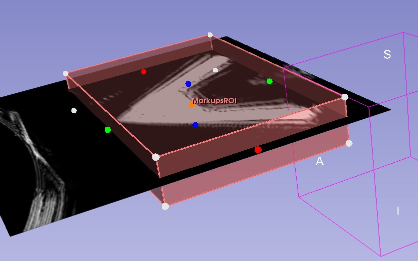
I get the following 2d view where the US frame fills only a small part of the window:
The region of interest has correct proprotions
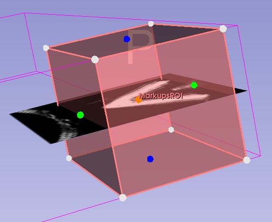
But after running 3D reconstruction, the volume isn’t rendered properly for some reason:
When I load .mhd file with Element Spacing = 1 1 1:
The US frame fills up all the space of the 2D Red window.
But the region of interest is squeezed and 3D reconstruction works (see the result in my first post), however; the volume has incorrect proprotions.
Could you please check if ImageToReference is changing over time when you move the sequence browser time slider, and if the values of the ImageToReference matrix make sense? You can see the matrix in the Transforms module if you select ImageToReference. The first three columns should have a norm of 0.2, and they should be orthogonal. Also check that Image does not have any extra transform in it. You can check that if you go to Volumes module and select Image (h_l_man_pyr-Image), and expand the section called “Volume Information”. The third value of dimensions should be 1, spacing should be 1 everywhere, origin should be (0,0,0), and the IJK to RAS matrix should be the identity.
If you check all these and they all look correct, then something might be wrong with the recorded data or the ImageToProbe calibration (should be part of ImageToReference). If you are recording data with PLUS, could you attach or copy the contents of your PLUS config file here?
I checked all the points you mentioned; everything seems to be fine. I think the problem is with maths, as I generate the transformations manually in my Python code instead of obtaining them from PLUS. You mentioned that the first three columns of the transformation matrix should have a norm of 0.2. Have I understood correctly that the transformation matrix should look like in the equation below?
And the content of my PLUS config:
In the PLUS config file, we never define ImageToReference. Image is rigidly linked to an ultrasound probe. But Reference is typically fixed to the patient. ImageToReference represents the motion of the image relative to the patient. It is always changing, so you cannot create a constant for it in the config file. That section is for constant transforms like ImageToProbe (because the ultrasound image is not moving relative to the ultrasound probe).
You say that you generate transforms in your Python code, you are not getting it from PLUS. I’m not sure I understand how is that possible. But in that case you just send the Image from PLUS without any transforms. Does your Python code obtains the tracking transforms directly from a tracker?
The PLUS config file that I use is from an official example on the website; for some reason, it does have an ImageToReference transform. However, as you said, it shouldn’t affect me in any way since I use only raw frames from the PLUS app and positions I receive from the joint encoders of my robot. After that, I generate transform matrices in Python code and embed them into the .mhd sequence file header. In my particular experiment where I scan in a linear manner, I assume the rotation matrix to be identity and change only the translation vector. If I understood you correctly, for preserving proportions, I should use an identity matrix multiplied by the element spacing - 0.2?
That ImageToReference was for convnience of display for a different image type. Honestly, it shouldn’t have been there in the first place, or at least named something else. You need to remove it, and send the Image in the Image coordinate system, because sending an ImageToReference in the Slicer scene will conflict with a tracking method. You can just send the Image in the Image coordinate system from PLUS. Untransformed.
I’m still not sure how you will get the tracking data for each frame.
ungiTamas Ungi thank you for the help! I multiplied rotation matrix by element spacing and managed to get the correct proportions.
I’m still not sure how you will get the tracking data for each frame
I just insert in my Python code the z-coordinates of my robot’s end-effector, obtained from joint encoders and inverse kinematics, into the translation vector of the 4x4 transformation matrix.
ElementSpacing, Offset, TransformMatrix are not used in sequence files, as they cannot vary for each frame.
You need to come up with a list of coordinate systems for your system, such as RobotBase, RobotEndEffector, Probe, Image, and Reference. Then make sure the ImageToReference transform is defined for each time point. The ImageToReference is defined if there is a chain of transforms between the Image and Reference coordinate systems. You can achieve this by specifying the following transforms:
If you want to use RobotBase coordinate system as your Reference coordinate system then you can put an identity <Transform From="RobotBase" To="Reference" Matrix="1 0 0 0 0 1 0 0 0 0 1 0 0 0 0 1"/> transform into CoordinateDefinitions. If the robot base is mounted to the patient bed then you may want to specify orientation that is aligned with patient anatomical axis directions. You may set this transform using landmark registration after the patient is positioned (e.g., by touching anatomical landmarks on the patient).
The probe calibration matrix, which tells the image pixel spacing and position and orientation of the image relative to a coordinate system that you define on the ultrasound probe goes into CoordinateDefinitions, too.
RobotEndEffector to Probe transform describes how the robot end effector grabs the ultrasound imaging probe (and you need to recompute each time you reposition the probe in the end effector). It goes into CoordinateDefinitions.
You compute RobotBase to RobotEndEffector from your robot kinematics model and joint encoders. It goes into the Seq_FrameNNNN_RobotEndEffectorToRobotBaseTransform fields in the sequence file header.