Ultrasound slice is not aligned with reconstructed volume

Hello,
I have 3 questions:

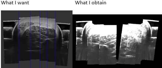
  1. Does anyone have an idea why my ultrasound images don’t match over my reconstructed volume?
    image
    I create my volume with PLUS, and the ImageToProbeTransform is included in the imageToReferenceTransform defined on the “prueba2.mha” file.

PlusApp-2.6.0.20190221-Win64\bin\VolumeReconstructor.exe --config-file=" prueba2-VolRec.xml" --image-to-reference-transform=ImageToReference --source-seq-file=" prueba2.mha" --output-volume-file=" prueba2Volume.mha"
image
image

  1. How I do to reconstruct my volume specifying the axes orientation:
    Axes are inclined, I would like to Have the red view on the same orientation that the first ultrasound image.
    image

Because I would like to extract SLICES from the compounding volume of ultrasound images and MASKS from the compounding volume of contours images.


image

If I’m not mistaken, the reconstructed volume is saved as slices throw an axis. do not?
If the reconstruction is done with the correct position and orientation of the axes, to recover the SLICES I should only read the mha format, similar to how it is done with a DICOM to obtain images. NOT?

  1. How I can plot the ultrasound probe like in this video:
    https://www.youtube.com/watch?v=2Oc_tCu_uzs
    image

I thanks you so much for your help
Vanessa GONZALEZ

Probably there is an RAS/LPS coordinate system difference. Configuration files are optimized for real-time reconstruction, when image is reconstructed in RAS coordinate system and sent to Slicer using OpenIGTLink.

If you reconstruct a volume using the VolumeReconstructor application then it reconstruct the image in RAS coordinate system and saves the image into a file. If you load an image file into Slicer then it is assumed to be in LPS coordinate system. To fix this inconsistency, either change the Plus configuration file to reconstruct in LPS coordinate system or apply this transformation matrix to the reconstructed image after you load it into Slicer:

-1  0 0 0
0 -1 0 0
0 0 1 0
0 0 0 1

You specify the coordinate system you want to reconstruct in by the image-to-reference-transform parameter.

You can find link to step-by-step instructions in the video comment. The .mrb scene file is included in Plus installation package.

Thank you Andras for your help, I tried to solve the problems in different ways before publish some stupid thing:

  1. I tried the matrix transformation solution to pass from RAS to LPS system, it worked really well. I tried also to: “change the Plus configuration file to reconstruct in LPS coordinate system”. But I thing, I am changing the wrong file.
    I suppose the plus configuration file, is the xml that I give as parameter of reconstruction. I define the transformation ReferenceToReference2. And I reconstruct the volume, but it does not to nothing.
    image

  2. I changed ImageToReferenceTransformations in the .mha file, one by one, and it worked!!! Thanks for the idea.
    I couldn’t make work reconstruction changing the parameter “ `image-to-reference-transform="ReferenceToReference3”, Plus volumeReconstruction says:
    image
    image

  3. I did not explain well. I did the step by step of the video, but I don’t find the way to print the probe.stl on realtime over my tracked images, I don’t need to simulate images, I have them already. If it is possible, could someone redirect me to the documentation, please? I’am sorry.

  4. “NEW ISSUE”: Images from my MHA file are charged as LIFO:
    image
    I extract the first image from my mha file, and I plot it with pyplot and they are good. Tracking Transforms matrices are created, taking as reference, the up-left corner.
    When I upload the images from my mha file in slicer I’m pretty sure they are charged as LIFO, so the bottom-rigth corner becomes the top-left corner.
    image
    I do not just need to flip it in the slicer-view (I did it), because in the 3dspaceview they are not flipped soo tracking and reconstruction is not well done.
    4.a I try changing the .mha parameter AnatomicalOrientation = RAI to RAS, TO LPS, etc. It didn’t work.
    I don’t want to save the images in the .mha as LIFO to be readed well, but if it is the only option I will do it.

Thank you and nice day.

The error message “Unable to allocate … elements of size …” means that you have run out of memory. You need to decrease the image resolution (increase output voxel spacing) or reduce the region of interest sweeped by the probe. Since Plus computed that you would need 434GB of memory, it may indicate that not just the spacing is off but the region of interest is too big, potentially because of errors in how the coordinate systems are defined.

Regardless you use real or simulated image source, you can use the exact same Slicer scene for visualization.

Make sure to set the PortUsImageOrientation tag correctly. See specification here. If you don’t know what orientation your device provides images in then you can find the correct port US image orientation value by trial and error. Note that if you change the image orientation (or resolution, etc.) then you need to recompute ImageToProbe calibration matrix.

First of all, thank you Andras for your answer and help.
I want to “Transfert images and tracking data from other software to slicer”.
I tried to reconstruct the volume with data of tracking and images obtained with other software. So I am building by myself the “.mha” file, because I am sure slicer is what I am looking for, but the reference systems are making me crazy.

Problem with the reference axes LPS, RAS, IJK and MF- UF
image

If PLUS algorithm works in RAS system, why it asks for an ‘UltrasoundImageOrientation = MF '? If I do not add this line on the mha file, it says during reconstruction with PLUS:
image

  1. So the question is: In the .mha file, should I see my image from the MF origin? Should I change trackingMatrices to my referenceSystem Mf? In this case I need to re-calculate calibration matrix also?, Not because it is just a relocation of the reference system, does not?

Can I do it multiplying just: MatrixTracker*”MatrixReposition”*Image?

With MatrixReposition=[[-1,0,0, width/2 ],[0,1,0,0],[0,0,1,0],[0,0,0,1]]?

  1. When I have any TransformMatrix in the .xml file: where it is applied? In MF or in RAS origin?

If I suppose that in PLUS the algorithm charge the image in RAS, so I have to write inversed each image in .mha file? And, with origin the bottom-Right, I applied ImageToIjkTransform=[[-1,0,0,width],[0,-1,0,height],[0,0,-1,0],[0,0,0,1]] to change the origin.

MatrixTracker*” ImageToIjkTransform”*Image?

But I obtain images not ovelaped:
image

I tryed different configurations of Transforms and the best result that I have is with matrix ImageToIjkTransform=[[1,0,0,-width],[0,-1,0,-height],[0,0,1,0],[0,0,0,1]]. But it has no sense.
image

I thank you your help.

Hi Andras,

I think the transform in Slicer for RAS to LPS would instead be

-1 0 0 0
0 -1 0 0
0 0  1 0
 0 0 0 1

Could you describe how to change the PLUS reconfig file to reconstruct in LPS instead of RAS? Just by including the above transform or is there an .xml property you can set?

Yes, sorry, it was a typo (fixed it now), indeed, RAS<->LPS conversion is done with a diag(-1,-1,1,1) matrix.

Plus can reconstruct a volume in any coordinate system you specify as the “To” coordinate system in ImageToReference transform (for example, if you specify ImageToReference="ImageToTracker" then the image will be reconstructed in Tracker coordinate system).