Operating system: Windows 64 bit
Slicer version: 4.6.2
Expected behavior: My .dcm file has clear values under the Pixel spacing and the Slice thickness,spacing between slices tags. So these values must be loaded onto image spacing under ‘volumes’.
Actual behavior: Image spacing goes to default value ie 1mm 1mm and 1mm.
Are there any other tags required for this field that I am forgetting to include in my dicom header? I cannot manually change it everytime as I am trying to integrate it with a different process.
You are making these dicom files yourself? If so maybe you have not encoded the elements correctly. You can try loading the sample data below and compare your data.
Also note if you are looking at the vtkImageData on a loaded node, it will have origin 0,0,0 and spacing 1,1,1 because there’s no way to encode orientation in a vtkImageData. Instead, location of the imaging data in patient space is encoded in the mrml IJKToRAS and transform elements.
Not exactly myself, but im just rearranging data. The DICOM header is stored as a dataset with elements. However, my data had a few elements itself as datasets. So I had to bring a few elements back into the main dataset. I was able to successfully bring proper values on slicer with respect to origin. This seems to take information from the Image position(Patient) Tag.
But even though the tags required for Spacing are now present as elements in the main dataset- Pixel spacing, slice thickness, and most of the other relevant data that is included in the header of the file you uploaded, The spacing still shows 1mm 1mm and 1mm. I am not using vtk.
Is there any information as to which tags exactly slicer draws the information from for image spacing? Intuitively it should be the two elements of Pixel spacing and the third element should be slice thickness.
PixelSpacing should always give the in-plane sizes in mm. Be sure it is in a valid dicom format of two DS values (basically decimal strings separated by backslash).
If you use dcmdump from dcmtk it should look something like this:
The out of plane spacing is defined by the distance between the ImagePositionPatient of adjacent slices, not by the SliceThickness, which can be different for a variety of reasons.
If Slicer (or ITK) can’t parse what your file contains you could end up with spacings of 1,1,1.
It’s a slightly different context, but this blog post gives you some background and context:
I’ve checked, and the slice thickness even coincides with the distance between the imagepositionpatient of adjacent slices.
And the pixel spacing seems to be the right format.Here is my ouput from python: I am using the pydicom toolbox.
The image is a multiframe image. Is that the problem? It had its image position patient of each slice under per frame functional group sequence! So maybe it is unable to find the proper spacing?
Multiframe DICOM images should be loadable in Slicer – is there any chance
you can share a deidentified example? Yes, having the ImagePositionPatient
values in the per-frame functional groups is the right place and Slicer
should be looking there.
Reading spacing correctly for multi-frame volumes has been added to ITK a couple of years ago. It might have broken since, as probably automatic testing of DICOM parsing is quite limited in ITK. Probably we should add tests for that in Slicer.
Unfortunately, I won’t be able to do that(share the image). This is an abdominal CT from Philips medical systems. I did download another standard multiframe from nema onto slicer and that does give proper values in the volume fields lifted right off the header but the rendered volume is well away from the origin of the RAS (The pink box) .
The nema image and this image does have a few differences. for example, the
(5200, 9229) Shared Functional Groups Sequence 1 item(s) ----
tag in my file does not have image orientation under the plane orientation sequence. My file has it just under all the per-frame functional groups. A couple of other extra tags were there under (5200,9299) for the nema image too! These were absent from mine.
However 5200,9229 does have the
(0028, 9110) Pixel Measures Sequence 1 item(s) ----
(0018, 0050) Slice Thickness DS: ‘3.00000’
(0028, 0030) Pixel Spacing DS: [‘0.597656’, ‘0.597656’]
tag which should be the only tag that contains relevant information.
Understood - it’s always toughest to debug dicom files that can’t be shared.
Since it looks like you know your way around the header with pydicom you should be able to easily generate a basic nrrd file. You can probably even make a .nhdr that is just a few lines of ascii and points to the raw data in the original dicom file.
It is a known issue with the datasets produced by some vendors, and the ITK reader is not robust enough to look for these attributes in the per-frame FG(s!) when they are missing in the shared FG.
I have been experiencing this DICOM spacing & thickness error recently on quite a few DICOM sets.
The files have the following tags in metadata:
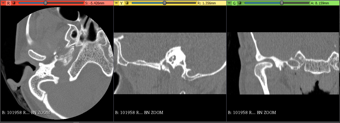
On load the error Irregular volume geometry detected (maximum error of 931.5 mm is above tolerance threshold of 0.001 mm) is displayed. The Volumes module shows the default spacing (1mm, 1mm, 1mm) and I must manually enter the correct values. Like @Shilpa_Ananth I am also looking to integrate this into another process so manual entry is not ideal. I did test Acquisition geometry regularization in Application Settings>DICOM, which does fix visualization in the slicer viewer. However, this created resolution errors when performing transformations on the volume.
Thanks for sharing the data and describing what you see. I can replicate the issue with your data. This happens when the underlying ITK reader cannot interpret your data as a proper volume with equal spacing in all axes. This can happen if there are missing slices or it can happen if the slice ordering is not consistent (SliceThickness and SpacingBetweenSlices are not used for this, only the per-slice ImagePositionPatient and ImageOrientationPatient). In this data there must be some issue that ITK doesn’t deal with or else the data is just wrong (I didn’t look at your data closely to see what the issue is here).
The Acquisition geometry regularization code detects this error and can correct for it when enabled. It creates a non-linear transform to put the slices back in the correct places as defined by the position and orientation.
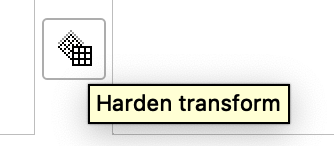
You can use the Harden Transform button in the Transforms module to apply the non-linear regularization transform to the data and then you can use it for other operations.
It’s a complex process actually, so the only real way to know is to look at the source code. The best short answer is it uses the ImagePositionPatient tags of the slices in a volume together with PixelSpacing.
At the center of things is some code that applies a number of heuristics. I’m not a huge fan of this code, but it was developed by people who had access to file types that are not available for testing.
Do you mind briefly explaining what Apply regularization transform actually does? I have used it to fix gantry tilt issues and to fix issues like the one described above, but I don’t understand what it is.
Also I notice that it is not enabled by default. It seems to do a good job of fixing errors so is there any reason why I shouldn’t leave this setting enabled all the time?
 Maybe I should try and convert this into separate images first!