Operating system:Windows10
Slicer version:4.10.2
Expected behavior:non distorted images
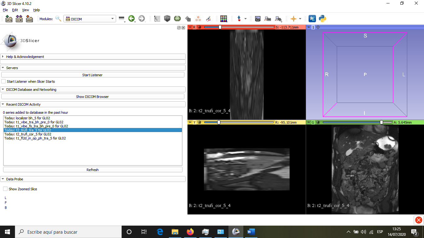
Actual behavior: distorted transversal image and non-distorted coronal image
Dear Sir or Madame:
I am Mar Collado from the University of Leeds. I am trying to use 3D slicer to analyse MRI images. I have DICOM images, that I have load into the 3D slicer 4.10.2. When I have tried to load the images of interest, the system gives me an error message: "Images are not equally spaced (a difference of -20 vs25 in spacings was detected). If loaded image appears distorted , enable ‘Aquisition geometry regularization’ in Application settings / DICOM / 2 DICOMScalarVolumePlugin. Please use caution. I have followed this instructions but then both images are distorted and so little that I cannot appreciate the organs in the images. Then, I restored the system as it was and the result is the same as the beginning (I am including a picture below so that you can see it). Can you help me, please?
Many thanks in advance
Kind regards
Mar
Thank you very much for your help. I followed your suggestion but the result is similar to what I obtained with the previous version. I am includding some images.
Hi,
I have just tried to load another DICOM images and no warning message appeared. So, I think that perhaps something happened during the acquisition of the images.
Many thanks for your time and sorry for any inconvenience
Kind regards
Mar
You could try and go to the Edit menu in the top left corner of the slicer window then choose “Application Settings”, then choose the “DICOM” tab from the list on the left, then under “Acquisition geometry regularization” choose “apply regularization transform”. You will have to close slicer and open it again the apply the settings. Then try and load the DICOM files again and see if that helps. The acquisition regularization can account for some problems like gantry tilt, missing slices, uneven slices etc.
Otherwise look through the images in the stack (with another DICOM viewer such as ImageJ) and see if there are any that are out of place such as a localizer image or maybe an image from another acquisition or something like that. If you find any images that don’t belong in the stack then remove them and try loading the rest of the images again in slicer.
Also if kind of looks like you are trying to load two series at once from the image above? Perhaps only load one series at a time?
I also came across this problem. I was trying to do segmentation on breast tomosynthesis. But when I loaded images they were distorted in other two planes.
I tried with your advice choose “apply regularization transform”. But still not worked.
Uploading: 1649352709(1).png…
Then I chekced my images on ImgaeJ, all of the sllices were in correct sequence. I could view the origninal image in ImageJ by importing image sequence.
If you provide an anonymized sample DICOM data set, then we can investigate it and fix any issues that may come up.
If you cannot share the data set but provide a detailed description (several screenshots, information on the imaging protocol, values of all Image Position Patient and Image Orientation Patient DICOM tags in the series, etc.) then we may be able to give a few suggestions. However, this requires much more of our and your time, and it is not guaranteed that we can guess correctly what the issue could be, so it would be much better if you could share the DICOM images.
Hi lassoan,
It’s my pleasure to forward you a anonymized sample.
But how can I attach this file to you? It seems in this forum there’s no such a funtion.
I’ve loaded the data set into the latest Slicer Preview Release and showed a 2D projection image (series 5) and a tomosynthesis volume (series 4) and it all looks good:
Oh, sorry, I updated my slicer version and now it works.
How to show the 3D view without segmentation like this?
I can only show segmentations it self by clikc “show in 3D”.
I did not segment the volume, just used volume rendering. Since the image has a very unusual intensity range, none of the presets work as is, but you need to adjust the transfer functions.
Sorry I’m new to use 3D slicer so I have more questions.
How to check the image’s intensity range?
Does 3D slicer have transfer fucntions to adjust the images’ intenstiy range?
Thanks a lot!
It is displayed with numerical values and a histogram in Volumes module. You can see the voxel values at the current mouse cursor position in the Data Probe (window at the lower left corner). But usually when you need to set anything that depends on the intensity values there is visual feedback you can rely on.
For slice views, a linear ramp function is used. You can shift the ramp horizontally and change the steepness (adjust window and level, a.k.a. brightness and contrast) numerically in the Volumes module or by setting the mouse mode to Window/Level and left-click and drag in the image. See detailed instructions here.
For direct volume rendering in 3D views, you have 3 transfer functions to edit (intensity, color, gradient), with more degrees of freedom, in Volume Rendering module.