Hello, all.
I’m not sure whether this is related, but I am seeing an odd dependence of the 3D rendering when toggling the ROI visibility (specifically the ROI that is always enabled to crop the displayed 3D rendering).
I realise that this issue is marked solved, but it may still be evident in the version of Slicer I’m using.
The images above look correct to me. Enable cropping and displaying the ROI are controlled by two different checkboxes. Enabling cropping when you display the ROI in the Volume rendering module is a convenience feature, because this is what users expect most of the time. If you can show/hide the ROI elsewhere (such as in Data module) without re-enabling cropping.
Are you saying that when I untick “Display ROI” in the Volume Rendering module that it automatically disables the cropping? That is not my experience, and it’s not what I’m reporting above. On top of that, I would not expect that hiding the ROI would disable the associated cropping unless the “Enable” tick-box became disabled (greyed out) whenever the ROI is hidden. And finally, I don’t think I would want them to be linked like that: it’s good to have two separate controls, so that I can view the cropped volume without being distracted by the white outlines (and coloured handles) of the ROI box.
In the case I presented, the cropping is (seemingly) unchanged, but the appearance of what’s within the ROI has changed. Are you saying that that is expected/intended behaviour? If so, could you clarify what the benefit of it would be?
ROI visibility and enabling a ROI to crop a volume are two independent properties. The only connection between them is a convenience feature in Volume Rendering module (enabling display will enable cropping).
Primary benefit of hiding the ROI (once you setup your cropping) is that it doesn’t clutter your screenshot and distract from the features you are trying to visualize. Making the ROI visible/hidden will not impact the cropping extend, if you enabled the cropping (see @lassoan’s answer above).
This discussion seems to be going around and around in circles.
The replies seem to be explaining the fact that hiding a ROI and enabling a ROI are two different things, and that it’s helpful that these two functions are separate. Thank-you for confirming that. I don’t dispute it; I agree with it. Unfortunately it doesn’t seem to have much to do with the issue I described above.
The issue I described is that hiding the ROI (while it is still enabled) caused a change in the appearance of the 3D rendering. Please inspect the screenshots carefully, especially in the lower half of the reconstruction. When the ROI is hidden the 3D rendering is less distinct. Nothing so far explains that. Hiding the ROI should either not affect the cropping (reconstruction should look identical) or else should potentially enlarge the reconstructed volume (reconstruction could look darker because of newly included voxels in the background or the foreground and/or could have larger extents); there is no reason I can see for the observed behaviour in which the extents look essentially the same but the reconstruction is lighter when the ROI is hidden.
Thanks for clarifying @DIV. I admit I looked at your images in your first post for a while and didn’t see obvious differences. Now that you say it’s darker in the lower half your question makes sense. Probably this is a difference with the zbuffer range or similar low level rendering issue. We may or may not be able to resolve this in Slicer if it’s a VTK issue. Best thing would be to make a reproducible example using public data. Even then if it’s only a small difference in a rare case it may be hard to prioritize, but of course we want the program to provide consistent results if possible.
Thanks, Steve.
This is the first time I noticed such a thing. It was ‘obvious’ to me (because of where my attention was directed), but I realise it may not have been obvious to others.
However, now that I have seen it this time I can look out for similar occurrences in future.
Going back to my original report (above), do you think this would be caused by the issue described by DRC at the start of this post, or does it seem like a separate thing?
It might be related, since both seem to come from ROIs but it’s hard to say. If you aren’t using VirtualGL it’s unlikely to be the exact same issue, but both may expose differences in the order of graphics commands leading to the driver being in slightly different states with or without the ROI visible.
That was a specific bug in VirtualGL, not in Slicer. Unless you are using VGL to render these images (on a remote server) than this thread is relevant. And looks like you are not even using GPU rendering.
That’s more-or-less why I posted here, instead of opening up a new thread.
Thanks for the explanations. I wasn’t sure what VirtualGL was, and when it would be used (e.g. by default, or only in special circumstances) but you’re right: I was doing everything on a local computer, and the setting shown in the Display panel of the Volume Rendering module in the screenshots is Rendering = “VTK CPU Ray Casting”.
In other instances I have also run with Rendering = “VTK GPU Ray Casting”, although I cannot comment on whether it makes any difference to the presently discussed issue. (I can keep this distinction in mind for future.)
There are many small differences in features and limitations of VTK’s internal volume rendering pipelines. When you change a rendering option, such as enable/disable depth peeling, then internally VTK switches to a different pipeline, which produces slightly different rendering results.
Reason for the slight change in your use case: Depth peeling is enabled by default in recent Slicer versions, but depth peeling is not activated until a semi-transparent actor appears in the field of view. This is why showing the semi-transparent ROI changes the volume rendering appearance in the screenshots above.
The differences between the pipelines will not go away completely, because maintaining full consistency between all rendering pipelines would be expensive (would take lots of developer time to implement all features for all pipelines) and often also technically impossible (e.g., GPU volume rendering is much faster but you may have more restrictions in how you implement the compositing function). I would recommend you to experiment with different volume rendering options and for each application choose the one that is the most suitable. If any specific limitation causes a problem for a use case then you can hire a developer or set up a software development contract with Kitware to get the missing feature implemented or problem/limitation fixed in VTK.
I am curious as to why the depth peeling is not configured to be ‘active’ all of the time, for (more) consistent rendering. Is it too computationally expensive (and/or disruptive to the user experience due to lags in video updating)?
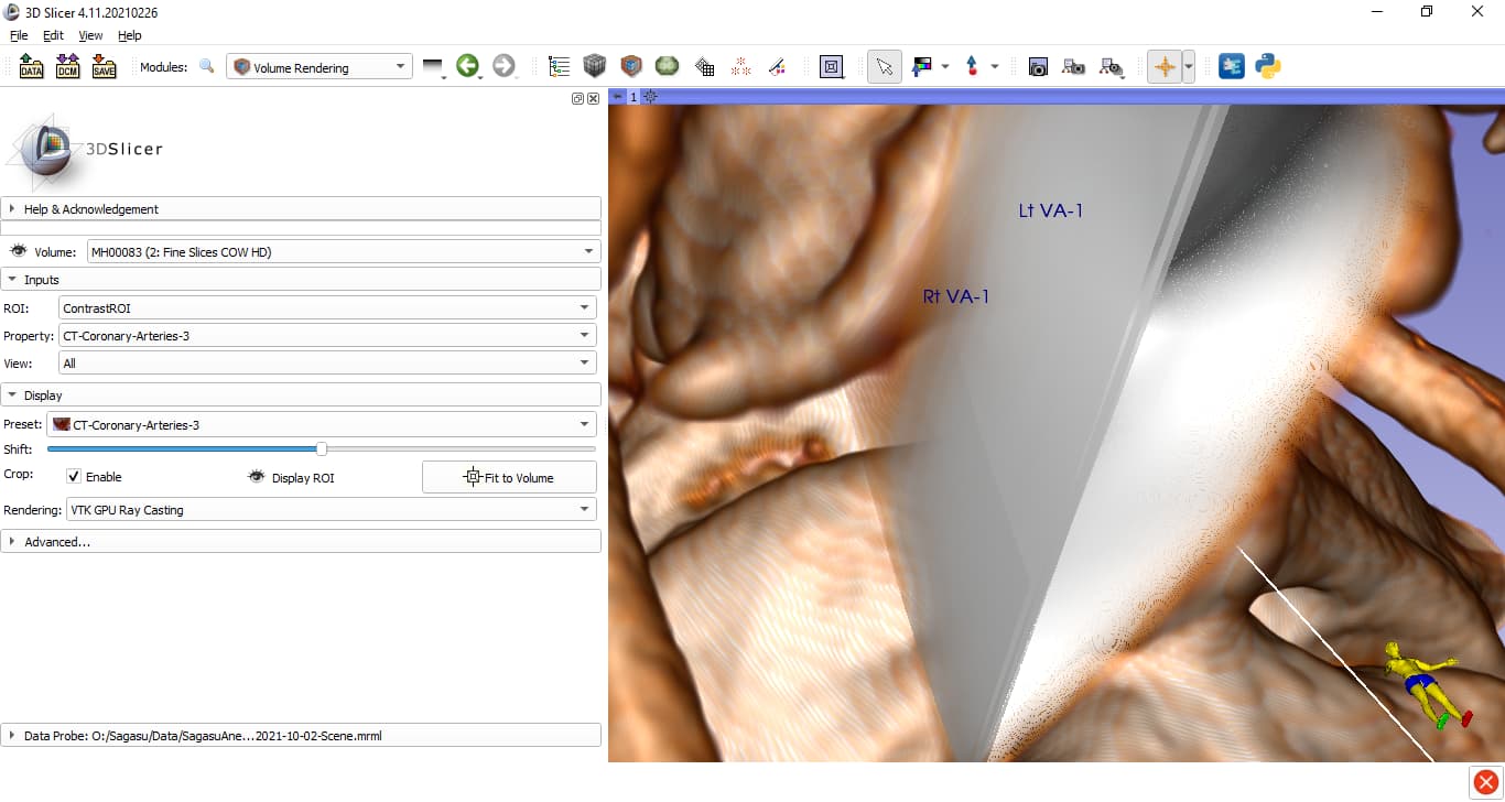
As the previous screenshots didn’t seem to illustrate the effect so clearly, here are another pair. (Which also demonstrates that it’s not a one-off quirk of one particular CT scan.)
VTK CPU Ray Casting (cropping enabled; with and without displayed ROI)
When rendering with the GPU the display of the ROI does not seem to have any effect at all on the 3D appearance.
Maybe depth peeling is always active (or always inactive) for the GPU pipelines?
In summary, the rendering in the two GPU screenshots is identical, albeit different to the two rendering results seen in the two CPU screenshots.