Operating system: windows 10
Slicer version:4.11
Expected behavior:
Actual behavior:
I want the control points in a centerline curve to have different sizes in 3d view and different sizes in sagittal view. I know I can use markups module to change glyph size for different point sizes but that changes it in both 3d view and other views. Is there any way to do this?
Can you tell a bit more about your use case?
Have you tried both absolute and relative glyph sizing mode?
You can always make nodes appear differently in various views by adding more display nodes and specify for each display node what views they are displayed in.
Hey @lassoan , yes I did try absolute and relative glyph sizing but that doesn’t apply here.
What I am trying to do is , first create a centerline curve using the vmtk extract centerline module. That gives me a centerline curve, the centerline curve has control points that I can view by toggling view in markups module(control points section). I want to display these control points with 5% glyph size in the 3d view on the centerline , but also 1% glyph size in the other views. So it is just the one vtkMRMLMarkupsCurveNode that I create.
As I wrote above, just create an additional display node for the 3D view. Set view node IDs in the display nodes select which views they render the markups node in.
Can you attach a screenshot that shows why you need different glyph size in slice and 3D view (how things look with 1% and 5%)? If this is may be a common need then we can address it in the Slicer core with a simpler solution than using multiple display nodes.
@lassoan ok ill try that. Yes I can attach a screenshot once I implement it. Thanks.
I meant please show how 3D and slice views look with a single display node now (two screenshots, one with 1%, one with 5%).
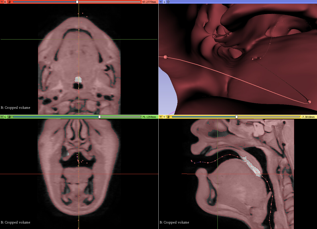

I see. Size variation in 3D view is a bit higher than usual due to the extreme wide angle field of view. Still the 5% size looks pretty good.
What is the reason for showing the control points? Do you expect your users to move the control points? Or you just want to allow then to click on it to jump to that position?
Well no, I actually wanted to view control points as I move through the centerline in endoscopy videos both in 3d view and others, but the control points look extremely small and are not visible during the video at 1% but they are in the other views. So I wanted to set it to 5% to make it look better in the endoscopy flythrough as well without changing how it looks in the other views.
If you don’t need to interact with the points then I would recommend to hide the control points. If you need to interact with them then the 5% looks good to me (but of course you can add the secondary display node if you want).
I’m sorry for not mentioning, but yeah I do think that displaying the control points will give the user additional functionality of jumping between visible points in the 3d view. One more thing: I know that I can set the glyph size using slicer.mrmlScene.GetDefaultNodeByClass(‘vtkMRMLMarkupsDisplayNode’).SetGlyphScale(5), how can I do this for absolute value? and how do I set absolute value to be on as default?
See documentation here for setting absolute/relative glyph size: Slicer: vtkMRMLMarkupsDisplayNode Class Reference
You can change the default properties for new nodes by modifying the default node (slicer.mrmlScene.GetDefaultNodeByClass(...)).